Section 26: XLII SLIDE-OUT
PA1553
8
member not parallel with the slide-out may
cause the inflatable seal to leave the wiper seal
or may reduce the inflatable seal and wiper seal
efficiency.
4 RACK
Slide-out movement is made by a system of
racks and pinions. There are two racks on each
slide-out.
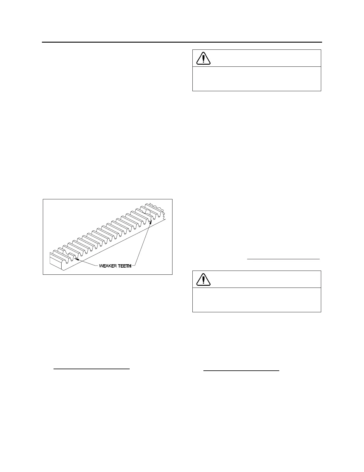
4.1 MAINTENANCE
Once a year, check the racks for broken or worn
tooth, especially the front slide-out racks. Also,
check the rack fastening hole teeth that are
weaker and might break (figure 10). Replace the
racks if excessive wear is present. Clean racks
from sand or other debris. Check that the racks
are properly secured. Check the backlash
between the gear and the rack. Excessive
backlash indicates rack wear.
FIGURE 10 : RACK
4.2 FRONT SLIDE-OUT RACK
REPLACEMENT
1. Remove the slide-out from the vehicle
(removal must be performed according to
the Slide-Out Removal Procedure. Ask to
your Prevost service representative).
2. From under the slide-out, unscrew all the
rack screws and remove the rack.
3. Install a new rack. Tighten the screws to a
maximum torque of 2 ft-lbs
. Use Loctite™
242 or equivalent product on threads.
4. Reinstall the front slide-out inside the
vehicle.
CAUTION
The counterboring required for recessed
screw heads reduce plastic thickness. Do not
torque higher than specified.
4.3 REAR SLIDE-OUT RACK
REPLACEMENT
1. Using the slide-out handheld control or the
manual override procedure (section 18, if
using the manual override procedure, do not
forget to deflate the inflatable seal
completely), extend the slide-out about one
foot.
2. From outside, unscrew and remove only the
first two screws of the rack to be changed.
3. Using the manual override procedure
(section 18) only, retract the slide-out to its
fully closed position.
4. Loosen the pinion keyless bushing of the
rack to be changed.
5. From under the slide-out, unscrew all the
rack screws and remove the rack.
6. Install a new rack between the slide out
structural rack seat and the pinion. Tighten
the screws to a maximum torque of 2 ft-lbs
.
Use Loctite™ 242 or equivalent product.
CAUTION
The counterboring required for recessed
screw heads reduce plastic thickness. Do not
torque higher than specified.
7. Tighten the pinion keyless bushing as
described in section 5.4.
8. Using the slide-out manual override
procedure only, extend the slide-out about
one foot.
9. Tighten the two remaining crews to a
maximum torque of 2 ft-lbs
. Use Loctite™
242 or equivalent product.
10. Using the slide-out handheld control switch
or the manual override procedure, retract
the slide-out to its fully closed position.
11. Re-inflate the air seal at 10 psi.
 Loading...


