Section 6: ELECTRICAL
PA1553
49
readings with published specifications in
Delco-Remy Service Bulletin 1G-186,
1G-187, or 1G-188. An alternator is
defective if it does not produce rated output
or if field windings are faulty. If the alternator
provides rated output, and field windings
check satisfactorily, the regulator should be
checked as covered under "Regulator
Checks".
8.1.2 Overcharged Battery
If the voltage setting as checked above is steady
and reasonably close to the specified value,
lower the setting by 0.3 volt and check for an
improved battery condition over a minimum
service period of 48 hours. If the voltage cannot
be adjusted to the desired value, proceed as
follows: where the alternator field is grounded
internally in the alternator as shown in figure 30
a shorted or grounded field or a defective
regulator can cause an overcharged battery.
The field winding can be checked as covered in
paragraph “Undercharged Battery”. If the field
winding is found to be correct, the alternator is
not defective, and the regulator should be
checked as covered under “Regulator Checks”.
8.2 REGULATOR CHECKS
Separate the cover from the base, and remove
the panel assembly from the cover. Carefully
note the location of all washers and lock
washers.
The component parts are keyed to figure 33.
Before making electrical checks, visually inspect
the components and make sure all soldered
connections are secure. Various electrical
checks with an ohmmeter can be made to
determine which components are defective.
The ohmmeter must be accurate, and should be
a scale-type meter with a 1.5 or 3 volt cell. Most
digital ohmmeters cannot be used to check
semiconductors. However, some digital
ohmmeters are specially designed to test
semiconductors and can be used to test
components in the regulator. Consult the
ohmmeter’s manufacturer for specifications
concerning the capabilities of the ohmmeter.
It is important that all of the following checks be
made. If a defective part is found, replace it
before proceeding with the remaining checks.
Be sure to make all the checks since more than
one component may be defective.
A defective regulator can be repaired according
to the following methods:
A) By changing the printed circuit board in the
regulator. Unscrew the retaining screws on
the printed circuit and remove it. Install a
new printed circuit board. This method is the
most commonly used.
B) By removing any retaining screws involved
and unsoldering the connections. When
resoldering, limit solder time to a minimum
as excessive heat may damage the printed
circuit board and component parts. However
good soldered connections are essential for
satisfactory operation. A resin core 63% tin
37% lead solder with a 360
o
F (182
o
C)
melting point is recommended along with a
soldering iron rated at 50 watts or less. Use
extreme care to avoid overheating. Before
checking the printed circuit board, remove
transistor TR1, which must be checked
separately. Connect the ohmmeter as
shown in figure 37, and then reverse the
ohmmeter leads to obtain two readings on
the same component. Use the middle scale
on scale-type meters on which the 300 ohm
value should be within or nearly within, the
middle third of scale.
Capacitors C1 and C2 = The ohmmeter should
read high and low on each capacitor. If not,
replace capacitor.
Diodes D1, D2 and D3 = Each diode should
give one high and one low reading. If not,
replace diode.
Resistor R2 = Turn voltage adjustment screw
(identified in figure 35) with ohmmeter
connecting each way. Reading should change
as slotted screw is turned. If not, replace R2.
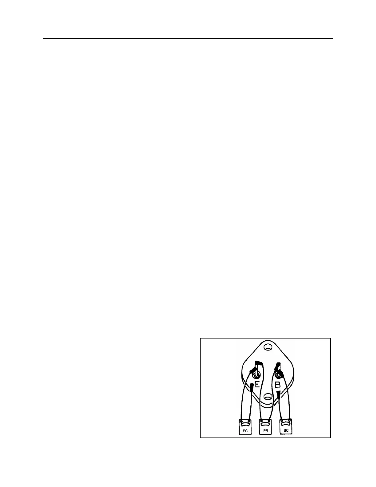
Transistor TR1 = See figure 37. Use the low
scale. Each of the three checks should read low
and high. If not, replace TR1.
FIGURE 37: CHECKING TRANSISTOR TR1 06081
 Loading...


