Section 26: XLII SLIDE-OUT
PA1553
9
5 PINION
CAUTION
Make sure all keyless bushings are tightened
to 125 lb-ft before moving the slide-out. Refer
to section 5.4 for torque wrench settings. A
lower torque value may cause the bushing to
slip on the shaft, and a higher torque value
may break the bushing.
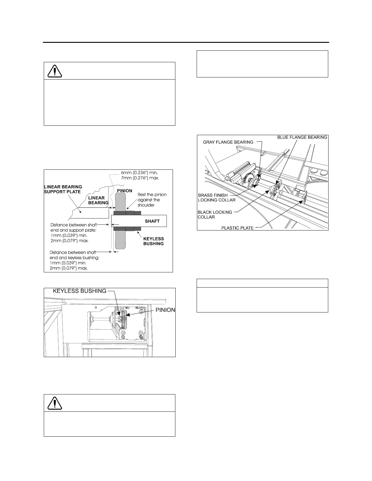
5.1 PINION AND KEYLESS
BUSHING POSITIONING
For proper functioning, respect the positioning
shown on the following figure.
FIGURE 11: PINION AND KEYLESS BUSHING
POSITIONING
FIGURE 12: PINION AND KEYLESS BUSHING AS SEEN
FROM EVAPORATOR COMPARTMENT
5.2 FRONT SLIDE-OUT SHAFT
PINION REPLACEMENT
CAUTION
Before reinstalling the pinion, clean the
following surfaces with alcohol to prevent
slippage.
o Pinion bore;
o Keyless bushing I.D. and O.D.;
o Shaft.
Before proceeding with the front slide-out shaft
pinion replacement, check the following
conditions:
- The locking collars located on the side of the
pinion being replaced are disengaged;
- The drive motor/gearbox assembly is
removed (see section 7.2);
FIGURE 13: MECHANICAL COMPONENTS (TYPICAL)
1. Loosen the keyless bushing (see section
5.4) of the pinion to be replaced. Slide the
pinion and its bushing out of the shaft.
Check the keyless bushing condition and
replace if needed.
NOTE
If necessary, loosen the blue and gray flange
bearing to move the pinion away from the
rack.
2. Assemble new pinion on the keyless
bushing and then slide on the shaft. Do not
tighten the bushing at this moment.
3. Properly position the shaft end in relation to
the linear bearing support plate (see
FIGURE 11) and then tighten the locking
collars to maintain the shaft in that position.
4. Position pinion and keyless bushing as
shown on FIGURE 11 and tighten the
keyless bushing as described in section 5.4.
5. Reinstall the drive motor/gearbox assembly.
 Loading...


