Section 26: XLII SLIDE-OUT
PA1553
25
• Check the SYSTEM DIAGNOSTIC menu
of the message center display (MCD).
Select FAULT DIAGNOSTIC and
ELECTRICAL SYSTEM. You should read
“no errors”. If an active error appears for a
module, this one was not reprogrammed.
In this case, repeat the procedure.
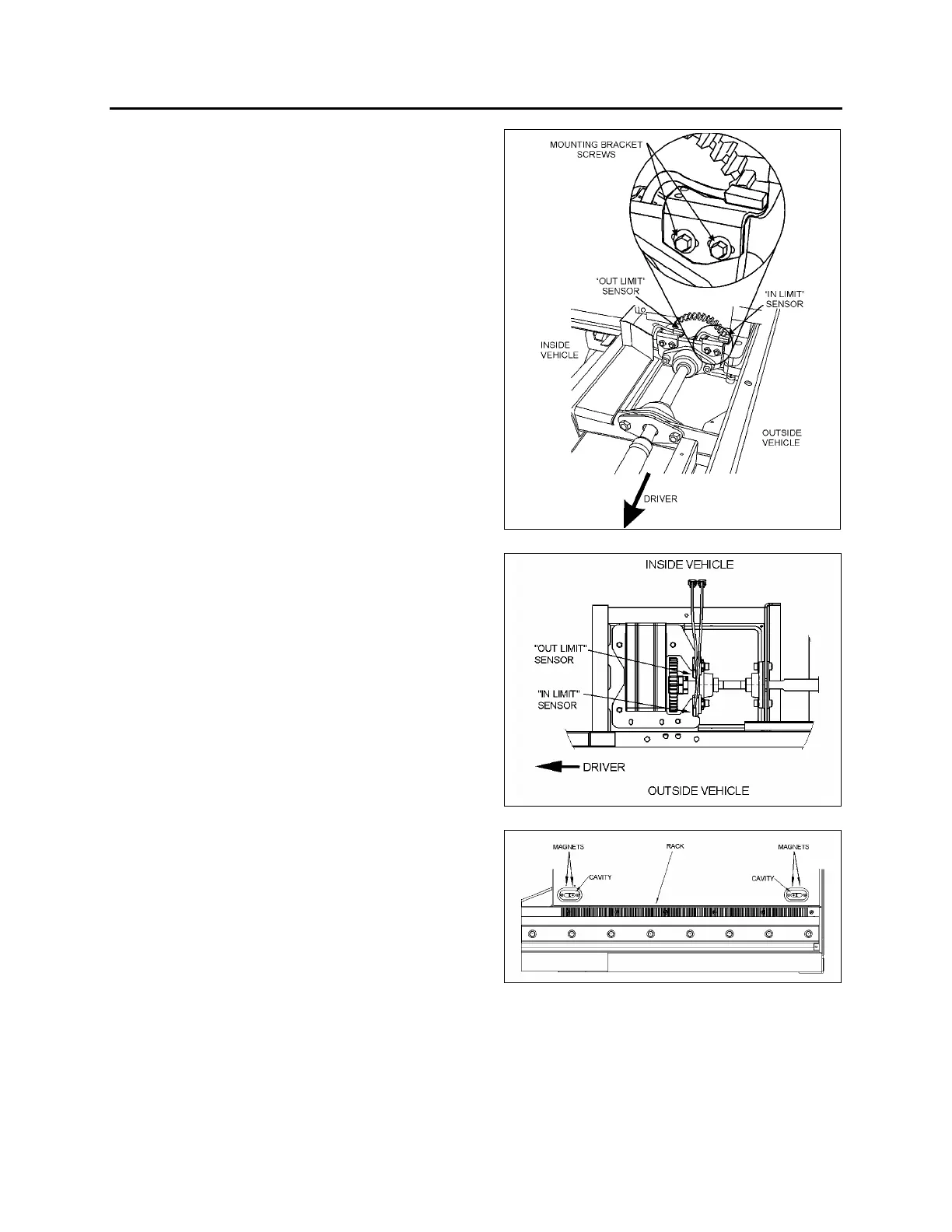
15.5 SLIDE-OUT LIMIT SENSORS
Two Hall-Effect sensors are used on each slide-
out to define end limit positions. The "in limit"
and "out limit" sensor detect two pairs of
permanent magnets fixed on the slide-out
underbody.
15.5.1 Maintenance and adjustment
The rear slide-out sensors are accessible from
inside of the vehicle, under the bed structure
while the front slide-out sensors can be reached
from the 3
rd
baggage compartment access
panel. To remove the sensors, unsnap them
from the mounting bracket.
To adjust the "in limit" sensors:
Prior to adjust the “in limit” sensors, assure that
the “in limit” stoppers are perfectly adjusted (see
section 1.2.2).
1. Retract the slide-out to its full “IN” position
with the “in limit” stoppers in contact with
their bearing surface.
2. Loosen the “in limit” sensor mounting
bracket screws and move back the sensor
completely (toward the inside of the vehicle).
3. Bring slowly the sensor toward the outside
of the vehicle until the light emitting diode
(LED) turns on. When it does, move it 0.079”
(2mm) further in the same direction and
tighten the mounting bracket screws.
4. Check if the “in limit” sensor is properly
adjusted. At the moment when the slide-out
stops during normal retraction, the “in limit”
stoppers must contact their bearing surface
(lower acetal plastic block).
Put white paint
on the “in limit” stopper before and
check if the acetal plastic blocks are
marked with paint.
FIGURE 37 : FRONT SLIDE-OUT SENSORS
FIGURE 38: REAR SLIDE-OUT SENSORS
FIGURE 39 : MAGNETS ON SLIDE-OUT UNDERBODY
To adjust the "out limit" sensors:
Prior to adjust the “out limit” sensors, assure that
the inner stoppers are perfectly adjusted (see
section 1.1).
 Loading...


