Repair and Testing Instructions for T1 Page 20
Alternator 0120 689 552 Edition 001
All rights rest with Robert Bosch Corp, including patent rights. All rights of use of reproduction and publication rest with R. B. Corp.
UA/ASV 04.12.98 T1ALTFinal.DOC
4. Using insulation tester KDAW 9983 (Bosch Number 0 986 619 110) or equivalent, apply 80 VAC to each of
the stator phase leads with one probe while the other probe is in contact with the exterior of the stator.
(Figure 13)
No continuity should be present. Any continuity between the stator phase leads and the exterior of the stator
indicates a breakdown of the stator insulation and a short to ground. If continuity is present, the stator must
be replaced.
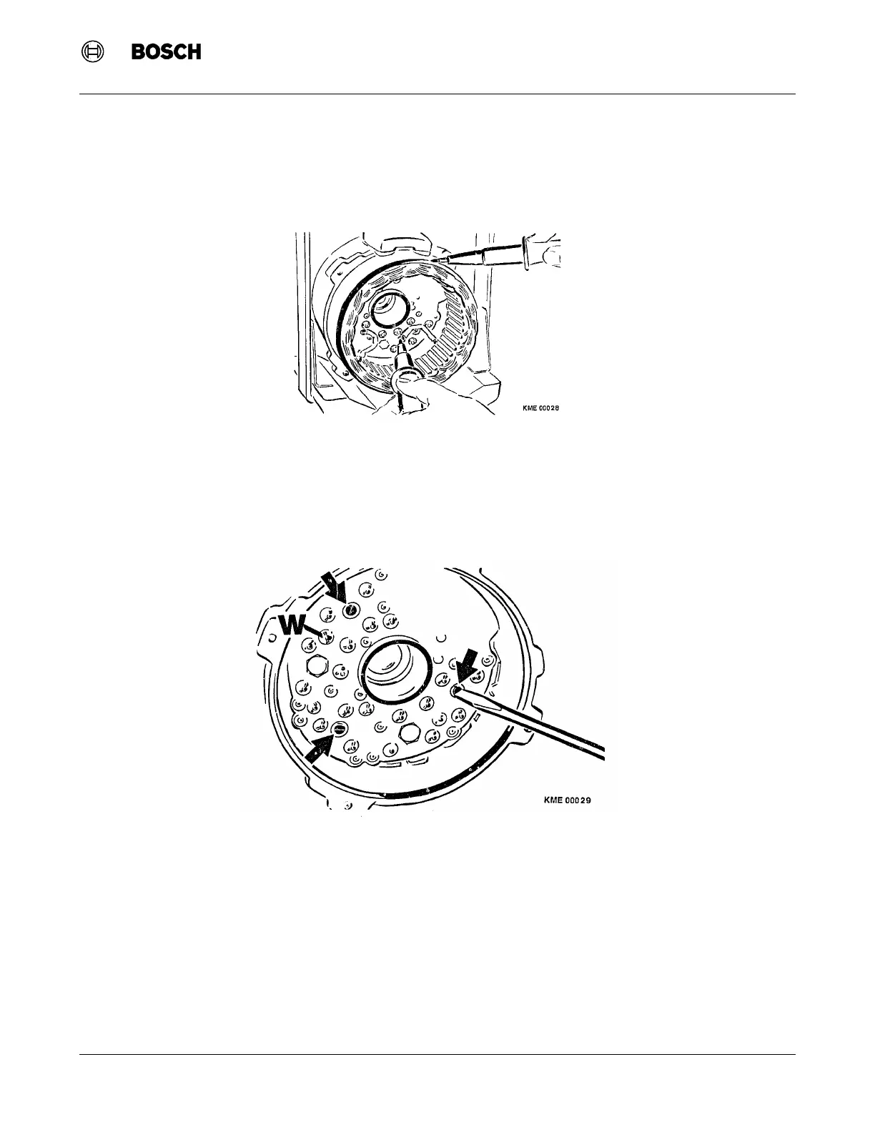
9.8 Rectifier Assembly Removal
1. Loosen and remove the three screws that hold the rectifier to the collector end shield. (Figure 14)
2. Unsolder the W terminal from the rectifier assembly.
3. Remove the nuts holding terminals B+, B- and D+ to the collector end shield.
Note: Do not attempt to remove the studs from the rectifier assembly. Terminals B+, B- and D+ are
permanently attached to the rectifier assembly. Terminal W is attached to the collector end shield. Do not
loosen Terminal W.
4. Remove the rectifier assembly from the collector end shield.
Figure 14 Rectifier Assembly Removal
Figure 13 Stator Insulation Testing
 Loading...


