SECTION 01: ENGINE
PA1553
5
2.3.1 VPOD Removal
1. Remove airline from VPOD.
2. Unplug harness connection.
3. Remove two bolts and one stud holding
VPOD assembly and bracket to engine
block.
2.3.2 VPOD Installation
1. Align VPOD assembly and bracket to
threaded holes in engine block; install two
bolts and one stud. Torque the M10 bolts
and M10 stud to 43-54 Lbf-ft (58-73 Nm).
Torque the M8 bolt to 22-28 Lbf-ft (30-38
Nm).
2. Connect airline to VPOD and tighten.
3. Plug harness connection into VPOD
assembly.
FIGURE 5: VPOD INSTALLATION 01147
NOTE
VPOD assembly is not serviceable, remove
and replace only.
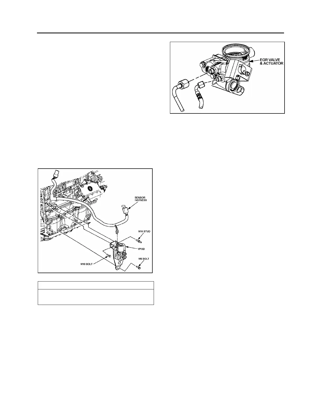
2.4 EGR HYDRAULIC VALVE
The hydraulic valve that controls the Exhaust
Gas Recirculation (EGR) system is located on
the same side as the VPOD but near the EGR
cooler (Fig. 1 & 6).
FIGURE 6: EGR VALVE & ACTUATOR ASSEMBLY 01148
2.5 SYNCHRONOUS REFERENCE SENSOR
The Synchronous Reference Sensor (SRS) is
an electronic component, mounted to the rear of
the gear case (Fig. 1). The SRS senses a raised
metal pin on the rear of the camshaft idler gear
and sends a signal to the ECM via a black
connector wire. The SRS sensor extends
through a hole in the gear case. It is positioned
near the rear of the idler gear. A bolt, inserted
through a hole in the SRS bracket, secures the
SRS assembly to the gear case.
The idler gear pin passes by the SRS as piston
number one crank pin reaches 45° before Top-
Dead-Center. The ECM uses this information to
determine engine speed.
The SRS is non-serviceable and must be
replaced as a unit. No adjustment is required.
2.6 TIMING REFERENCE SENSOR
The Timing Reference Sensor (TRS) is an
electronic component mounted on the left side
of the gear case (right side of coach), near the
crankshaft centerline. The TRS is positioned
near the timing wheel gear teeth and extends
through an opening in the gear case. A bolt,
inserted through a hole in the TRS bracket,
secures the TRS assembly to the gear case.
The TRS connector is gray. The TRS sends a
signal to the ECM, this signal is generated by a
series of evenly spaced special teeth on the
timing wheel. A tooth passes by the TRS as
each cylinder crank pin reaches 10° before Top-
Dead-Center.
The ECM uses these signals to determine
injector solenoid operation time. The TRS is
non-serviceable and must be replaced as a unit.
No adjustment is required.
 Loading...


