Section 03: FUEL SYSTEM
PA1553
11
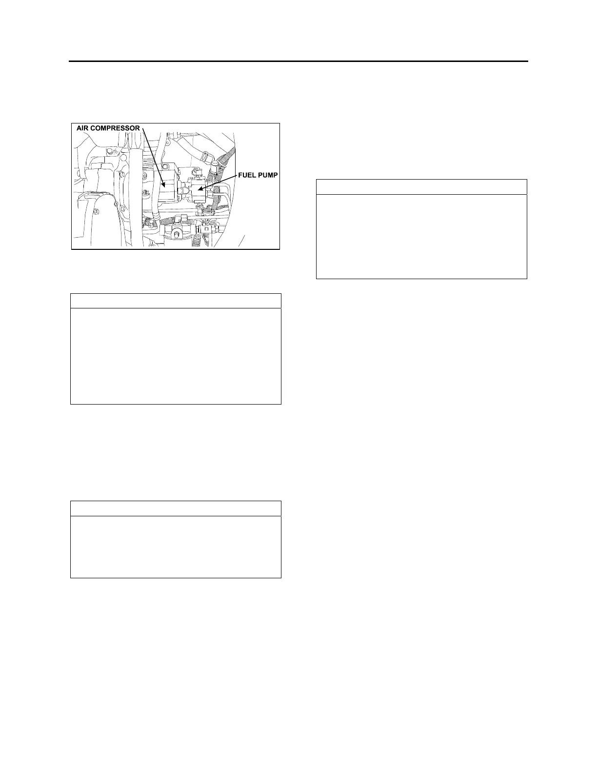
7. FUEL PUMP INSTALLATION
The fuel pump is driven off the rear of the air
compressor.
FIGURE 10: FUEL PUMP LOCATION
03053
1. If removed, install inlet and outlet fittings in
the cover of the fuel pump.
NOTE
New fittings have sealant already applied.
When reusing fittings, coat the threads lightly
with Locktite Pipe Sealant, Detroit Diesel
number J 26558-92, or equivalent, before
installing. To prevent sealant from entering
fuel system, do not apply to the first two
threads of the fitting. Do not use Teflon tape
or paste on the fittings.
2. Install drive coupling in drive hub of the fuel
pump. Install a new gasket to the mounting
flange of the pump.
3. Index the drive coupling with the drive hub on
the end of the air compressor crankshaft and
align the pump mounting bolt holes with
those in the air-compressor rear cover.
NOTE
When correctly positioned, the outlet fitting on
the pump should be in approximately an 8
o'clock position when viewed from the rear,
and the drain opening in the pump body
facing down.
4. Seat the fuel pump squarely against the air
compressor. Pilot the flange on the pump
body, in the opening in the rear cover of the
compressor. Install three mounting bolts and
tighten them to 22-28 Lbf-ft (30-38 Nm).
5. Connect the fuel inlet and outlet lines to the
fuel pump and tighten.
6. Prime engine fuel system before starting
engine to ensure pump seal lubrication and
prompt engine starting.
8. FUEL OIL SPECIFICATIONS
The quality of fuel oil used for high-speed diesel
engine operation is a very important factor in
obtaining satisfactory engine performance, long
engine life and acceptable exhaust emission
levels. The fuel oil should meet ASTM
designation D 975. Grade 1-D is recommended,
however grade 2-D is acceptable.
NOTE
These fuel grades are very similar to grade
DF-1 or DF-2 of Federal Specifications
VV-F-800. For detailed fuel
recommendations, refer to publication "Engine
Requirements-Lubricating Oil, Fuel, and
Filters" #7SE270 available from Detroit Diesel
Distributors.
9. AIR CLEANER (DRY TYPE)
The vehicle is equipped with a dry-type
replaceable element air cleaner, located in the
engine compartment. Access the air cleaner
through the engine R.H. side door. Engine air
enters the air cleaner through (2) two intake
ducts located just above engine side doors. It
then flows through a pre-cleaner and finally
through the air cleaner. The pre-cleaner
removes dust and moisture by means of a
discharge tube at the bottom of the element. It is
in series with a replaceable impregnated paper
filter element (air cleaner).
9.1 PRE-CLEANER SERVICING
The pre-cleaner is designed to be self-cleaning;
however, it should be inspected and any
accumulated foreign material removed during
the periodic replacement of the impregnated
paper filter element.
9.2 AIR CLEANER SERVICING
Stop the engine, open the R.H. side engine
compartment door, and loosen the wing nut
retaining the air cleaner element to the air
cleaner. Remove the element by pulling on the
handle in the center of the air cleaner element.
Install cleaner element as follows:
1. Inspect the gasket-sealing surface inside the
air cleaner. It must be smooth, flat and clean;
2. Install the air cleaner element;
3. Make sure that the element seals securely;
 Loading...


