SECTION 01: ENGINE
PA1553
25
11. JAKE BRAKE
Refer to both "The Jake Brake Troubleshooting
and Maintenance Manual" and "Installation
Manual for Model 790 Engine Brakes" for
troubleshooting and installation procedures.
They are annexed at the end of this section.
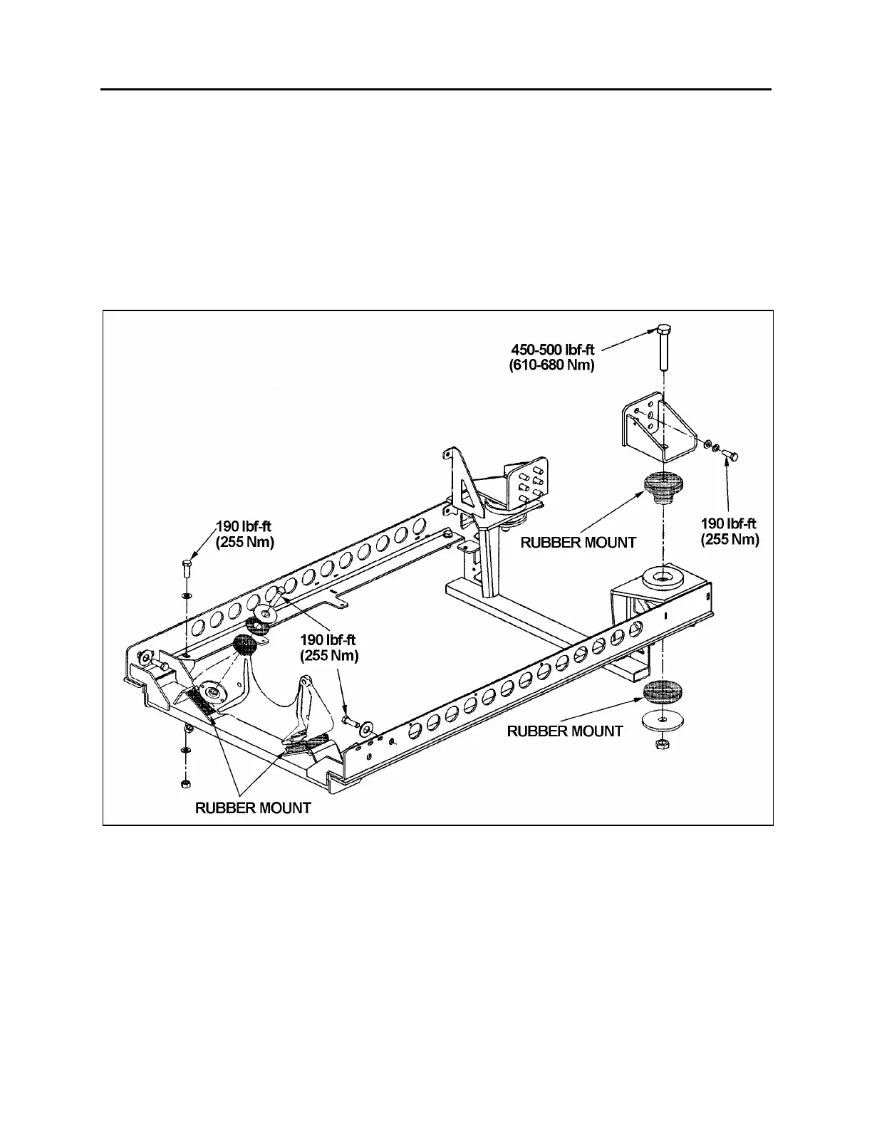
12. ENGINE MOUNTS
The power plant assembly is mounted to the
cradle by means of rubber mounts.
Two rubber mounts are used at the front of the
engine while two others are mounted on each
side of the flywheel housing (Fig. 18).
It is recommended that new rubber mounts be
installed at each major overhaul.
FIGURE 18: POWER PLANT CRADLE INSTALLATION 01140
 Loading...


