Section 06: ELECTRICAL
PA1553
18
3.5.1 Visual Inspection
1. Check the outside of the battery for a broken
or cracked cover or case that could permit
loss of electrolyte. If obvious physical
damage is noted, replace the battery.
2. Check for loose terminal posts, cable
connections, damaged cables, and for
evidence of corrosion. Correct conditions as
required before proceeding with tests.
3.5.2 Removing Surface Charge
Disconnect cables from the battery and attach
alligator clamps to the contact lead pad on the
battery as shown in figure 17. Connect a 300
ampere load across the terminal for 15 seconds
to remove surface charge from the battery.
3.5.3 Load Test
This test is one means of checking the battery to
determine its ability to function as required in the
vehicle.
To make this test, use test equipment that will
withstand a heavy electrical load from the
battery, such as a carbon pile resistor or other
suitable means.
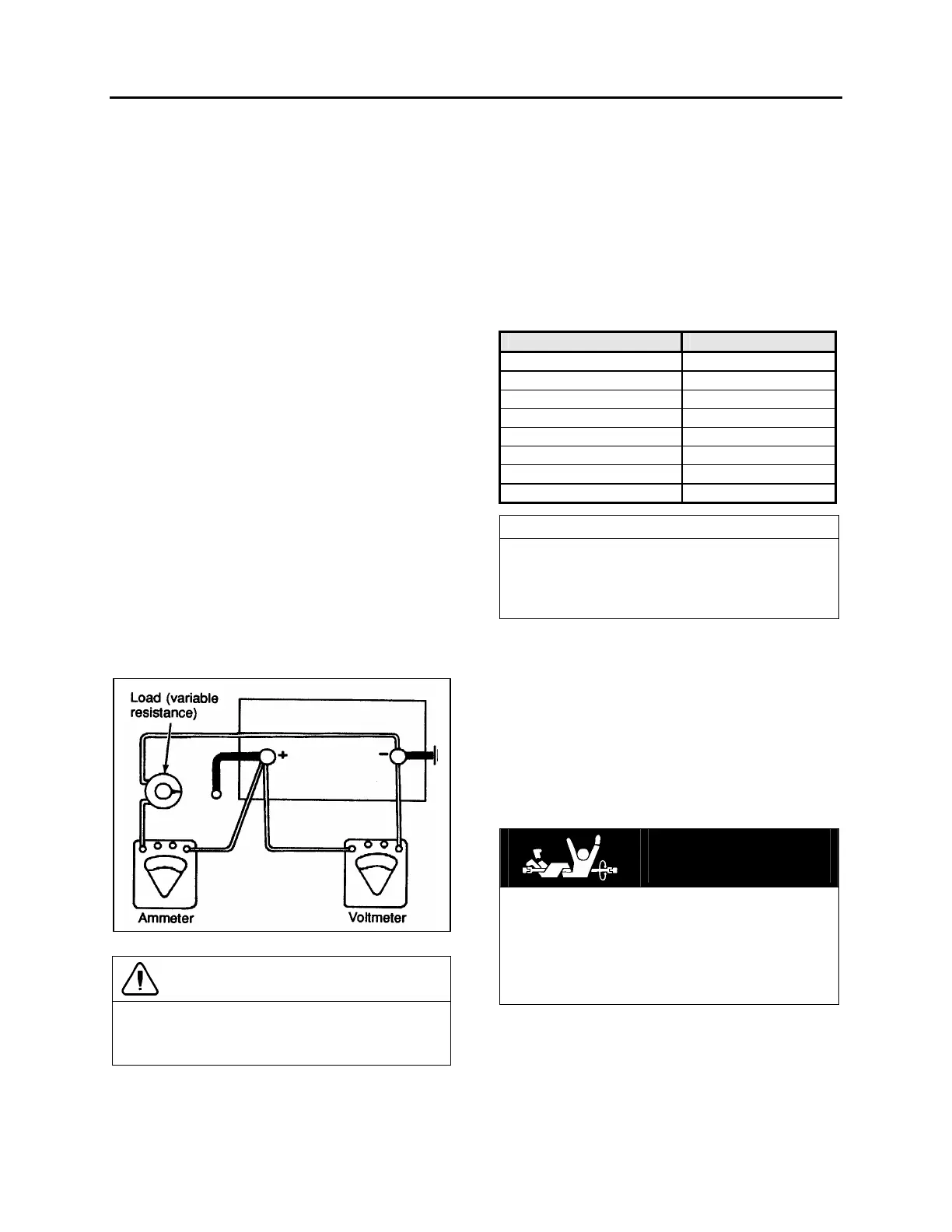
1. Connect a voltmeter, ammeter, and a
variable load resistance as illustrated in
figure 16.
FIGURE 16: LOAD TEST 06064
CAUTION
Observe polarity of the meters and the battery
when making connections, and select the
correct meter range.
2. Apply a 290 amperes load to the battery for
15 seconds.
3. With an ammeter reading specified load,
read voltage. The voltage should be at least
9.6 volts. Disconnect the load. If the
voltmeter indicates 9.6 volts or more, the
battery is good. If the voltmeter reading is
less than 9.6 volts, replace the battery. This
voltage is to be used for battery ambient
temperatures of 70ºF (21ºC) and above. For
temperatures below 70ºF (21ºC), refer to the
following "Voltage and Temperature Chart".
Voltage and Temperature Chart
Ambient Temperature Minimum Voltage
70ºF (21ºC) and above 9.6
60ºF (16ºC) 9.5
50ºF (10ºC) 9.4
40ºF (4ºC) 9.3
30ºF (-1ºC) 9.1
20ºF (-7ºC) 8.9
10ºF (-12ºC) 8.7
0ºF (-18ºC) 8.5
NOTE
The accuracy of this test procedure is
dependent upon close adherence to the
proper load, time and temperature
specifications.
3.5.4 Testing Battery Cables
Check all cable ring terminals and connections to
determine if they are in good condition.
Excessive resistance, generally caused by poor
connections, produces an abnormal voltage drop
which may lower voltage at the starter to such a
low value that normal operation of the starter will
not be obtained. An abnormal voltage drop can
be detected with a low-reading voltmeter as
follows:
DANGER
To prevent the engine from starting, the DDEC
engine circuits, which are protected by
breakers (CB-1 & CB-2) located in the circuit
breaker panel, must be deenergized during
these tests; afterward toggle yellow lever
upwards to reset the circuit breakers.
1. Check voltage drop between grounded
(negative) battery terminal and vehicle frame
by placing one prod of the voltmeter on the
battery terminal and the other on a good
ground (unpainted surface) on the vehicle.
With the starter cranking the engine at a
 Loading...


