Section 14: STEERING
PA1553
7
SERVOCOM Repair Manual" and “ZF-
SERVOCOM Operating, Servicing/
Maintenance and Inspection Instructions”
annexed to this section, under heading "Setting
The Steering Limiter").
CAUTION
Never maintain the relief pressure for more
than 5 seconds, since damage to the power
steering pump may occur.
10. STEERING LINKAGE ADJUSTMENT
The steering linkage consists of tie rods
connected to the bell crank and the steering arm
at the left side of the bus shell, and to the idler
arm and steering arm at the right side of the bus
shell.
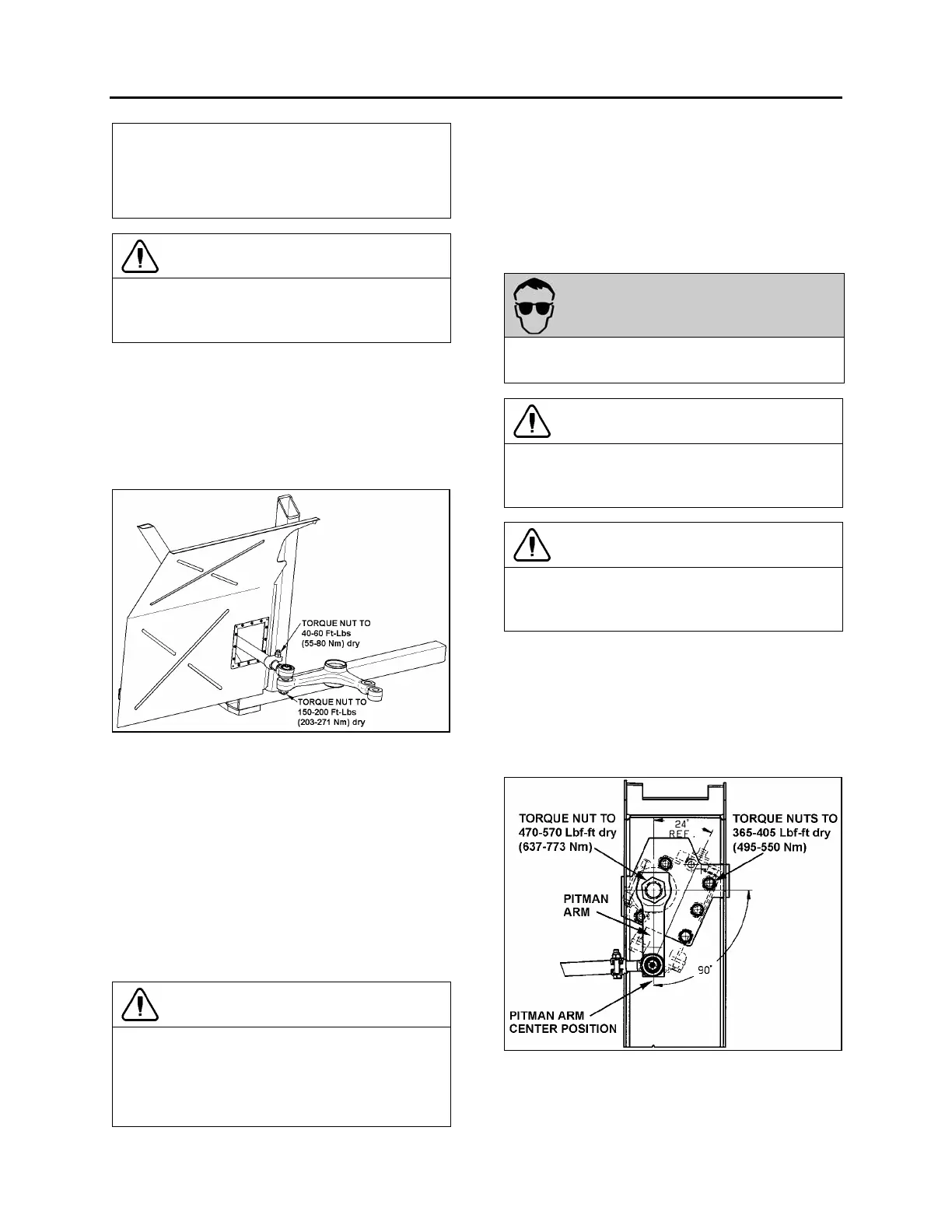
FIGURE 6: DRAG LINK TO BELL CRANK CONNECTION
Perform lubrication according to "DANA SPICER
NDS Axles Lubrication and Maintenance"
annexed to section 11 "Rear Axles".
Drag link ends are provided with grease fittings.
Under normal conditions, these should be
serviced every 6,250 miles (10 000 km). Refer to
section 24 "Lubrication".
Steering linkage pivot points should be checked
each time they are lubricated. Looseness can be
visually detected while rotating the steering wheel
in both directions. Replace defective parts.
CAUTION
Front wheel alignment should be checked and
adjusted if necessary, any time a component of
the steering system is repaired, disassembled
or adjusted. Refer to section 16 "Suspension"
under heading 7. "Front End Alignment".
11. PITMAN ARM
11.1 REMOVAL
1. Remove cotter pin, nut and washers from
drag link ball stud at pitman arm.
2. Disconnect drag link from pitman arm, using
jaw style pullers (pressure screw type).
WARNING
Always wear approved eye protection when
operating pullers.
CAUTION
Do not drive (hammer in) pitman arm on or off
pitman shaft as this can damage the steering
gear.
CAUTION
Heating of components to aid in disassembly is
not allowed because it has a detrimental effect
on axle components and steering linkages.
3. Using a cold chisel, undo punch mark that
locks fixing nut to the pitman arm.
4. Remove pitman arm fixing nut.
5. Check the radial position of the pitman arm in
relation to the sector shaft prior to removal of
pitman arm.
FIGURE 7: PITMAN ARM ADJUSTMENT 14057
6. Add reference marks to the arm and shaft if
necessary to ensure correct alignment at
reassembly.
 Loading...


