Section 26: XLII SLIDE-OUT
PA1553
7
2 SECURITY PIN
During normal ride, the slide-out cannot extend
by itself because the 740:1 ratio speed reduction
worm gear type gearbox system is not
reversible, the output shafts are self-locking. The
security pin purpose is to lock the slide-out in
retracted position if an accident occurs. It is built
to stand a great lateral acceleration of the slide-
out.
The system consists of a stainless steel pin
connected to a single action/spring return
pneumatic cylinder (FIGURE 8). The pin
engages in the slide-out receptacle with
releasing of the parking brake. A knocking sound
may be heard at this moment. An O-ring is
located at the base of the pin housing to reduce
knocking when the pin retracts. The lower hole
on the pin housing permits water to drain. The
upper hole permits to insert a small screwdriver
to prevent the pin from rotating when the air
cylinder has to be removed.
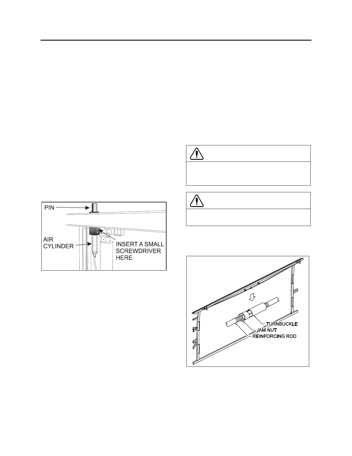
FIGURE 8: SECURITY PIN AIR CYLINDER REMOVAL
2.1 MAINTENANCE
Inspect air cylinder and fitting for air leaks.
Periodically, check that the pin retracts and
engages in the receptacle as it should when the
parking brake is applied or released. To do slide-
out, the slide-out must be in its full “IN” position
with the engine running. If the pin produces
excessive knocking when it engages with
releasing of the parking brake, reduce air
cylinder speed by adjusting the air flow regulator
on the pneumatic control panel (FIGURE 29,
item 11).
2.2 AIR CYLINDER REPLACEMENT
1. Assure the parking brake is applied.
2. Disconnect the cylinder air tubing from the
2
nd
baggage compartment (front slide-out) or
under the bed structure (rear slide-out).
3. Using a wrench at its lower end, unscrew
the air cylinder from the pin housing.
4. Insert a small screwdriver through the pin
and housing to prevent rotation of the pin an
then, unscrew the cylinder rod from the pin.
5. Transfer the fitting on the new cylinder.
Place Teflon on threads.
6. Cylinder installation is like removal but in
reverse order.
3 ROOF REINFORCING ROD
CAUTION
The front slide-out roof reinforcing rod may
have to be adjusted after a load variation
inside the vehicle or on the top of the vehicle.
CAUTION
Always lock the turnbuckle using the jam nut
to prevent loosening.
The roof reinforcing rod is located on the upper
horizontal member of the front slide-out opening
and is welded on the roof arches (figure 9).
FIGURE 9 : FRONT SLIDE-OUT ROOF REINFORCING
ROD
This rod allows an adjustment between the slide-
out horizontal member and the roof. When
screwing the turnbuckle, the roof is moved
upward, and vice versa. Use this rod to adjust
the horizontal member parallel to the slide-out. A
 Loading...


