Section 12: BRAKE AND AIR SYSTEM
PA1553
9
2. Turn the adjustment screw clockwise to
increase the pressure slowly until the re-
quired pressure setting is reached. Tighten
the locking nut.
3. Remove pressure gauge and replace dust
cap on the air pressure check valve.
10. AIR COMPRESSOR (BA-921)
The air compressor is located on starter side of
the engine, on the rear of the engine gear case
(Fig. 8). Its function is to provide and maintain
air under pressure to operate devices in brake
and air systems.
This air compressor also drives the engine fuel
pump which is bolted to the rear end of the
compressor. The compressor crankshaft is
designed to accept a drive coupling which is
placed between the compressor and fuel pump.
The compressor is driven by the bull gear, and
is water cooled. Engine coolant is fed to the
compressor through a flexible hose tapped into
the block water jacket and connected to the rear
of the compressor. Coolant returns from the top
of the compressor (governor side) through a
flexible hose to the engine pump.
The air is taken from the air intake manifold and
entered in the top of the compressor. The
compressed air is pushed into the discharge line
located on side of the compressor, which sends
air to the air dryer. Lubricating oil is supplied to
the compressor by a line from the cylinder block
oil gallery connected to the air compressor.
Lubricating oil returns to the engine crankcase
through the air compressor drive assembly.
Maintenance and repair information on the
Bendix BA-921 air compressor is supplied in the
applicable booklet annexed to this section under
reference number SD-01-676.
FIGURE 8: AIR COMPRESSOR LOCATION 03061
10.1 COMPRESSOR REMOVAL AND
INSTALLATION
1. Exhaust compressed air from air system by
opening the drain valve of each air tank.
2. Drain the engine cooling system. See
Section 5: "Cooling System".
3. Identify and disconnect all air, coolant and
oil lines from the compressor assembly.
4. Access the compressor by the engine R.H.
side compartment. Remove the four
compressor mounting bolts and the two fuel
pump support bracket bolts.
5. Slide air compressor rearward to disengage
the hub from coupling. Remove the air
compressor.
Reverse removal procedure for installation.
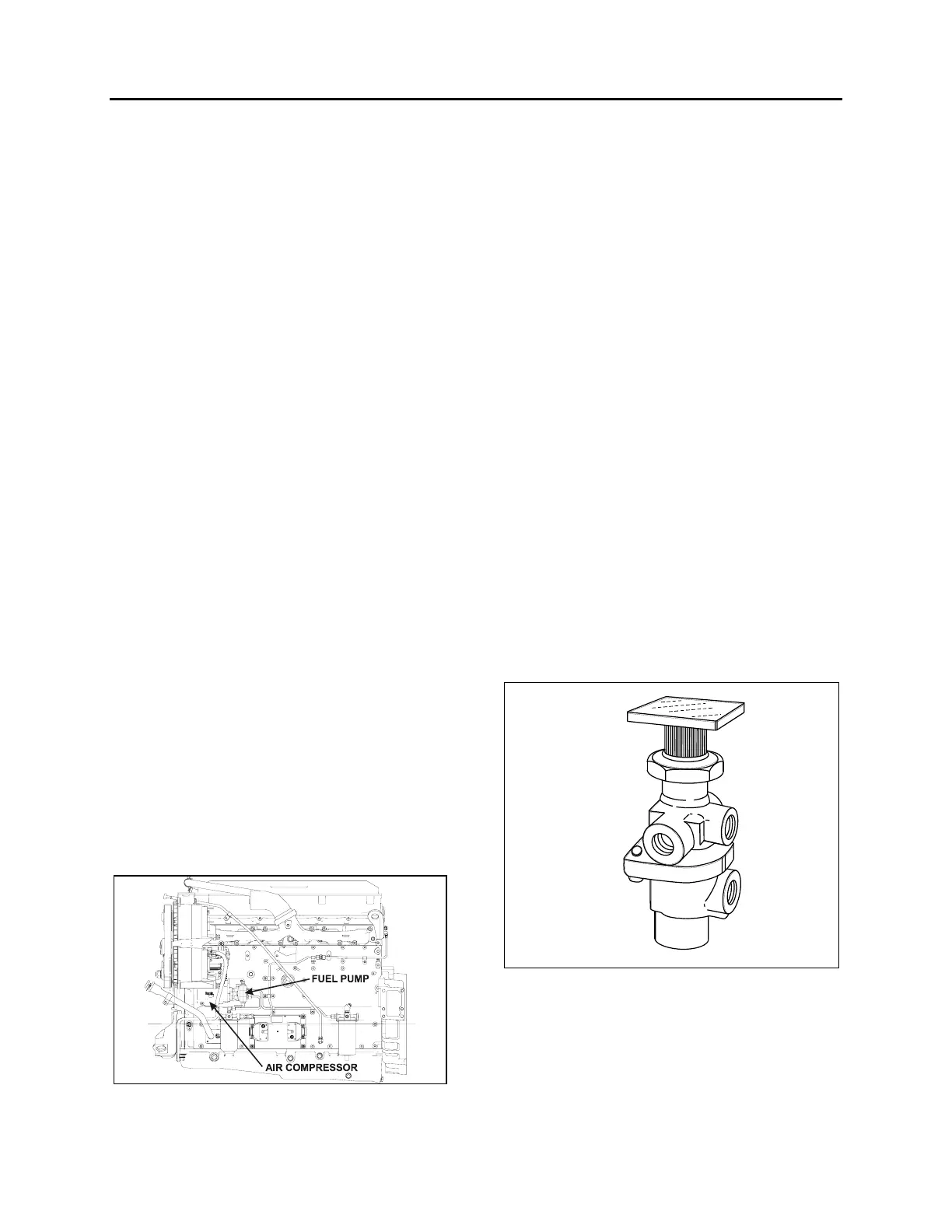
11. EMERGENCY/PARKING BRAKE
CONTROL VALVE (PP-1)
A push-pull control valve mounted on the L.H.
lateral console is provided for parking brake
application or release. The spring brakes are
self-actuated whenever the control valve supply
pressure drops below 40 psi (275 kPa). In the
UP position, brakes are ON. In the DOWN
position, brakes are RELEASED. A protective
case around the knob prevents accidentally
releasing the brakes.
FIGURE 9: PP-1
12142
Maintenance and repair information on this valve
is supplied in the applicable booklet annexed to
this section under reference number
SD-03-3611.
Remove the valve the following way:
1. Drain the air system.
 Loading...


