Section 12: BRAKE AND AIR SYSTEM
PA1553
26
NOTE
The ABS system is inoperative at speeds
under 4 mph (6 Km/h). Illumination of ABS
telltale indicator at these speeds is normal.
CAUTION
Disconnect the ECU or pull the ABS fuse
before towing vehicle.
29.1 TROUBLESHOOTING AND TESTING
For troubleshooting and testing of the vehicle's
anti-lock braking system, refer to Meritor Wabco
Maintenance Manual MM-0112: “Anti-Lock
Braking System (ABS) for Trucks, Tractors and
Buses", at the end of this section. Use
dashboard Message Center Display (MCD)
Diagnostic Mode for troubleshooting and repair.
29.2 ABS COMPONENTS
The main components of the ABS system are
listed hereafter. Refer to each component for its
specific function in the system and for proper
maintenance.
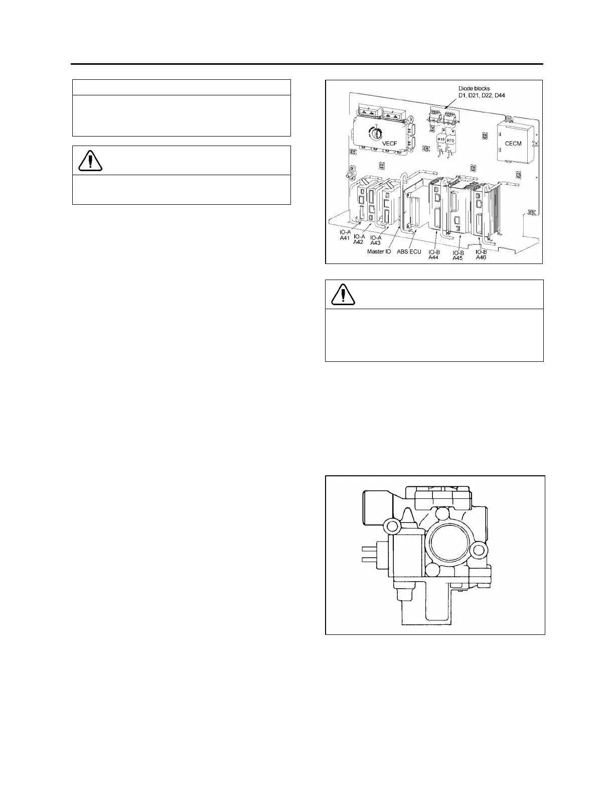
29.2.1 Electronic Control Unit (ECU)
This control unit is located in the front service
compartment, (refer to figure 42 for location).
According to the data transmitted by the sensors
(number of pulses/sec is proportional to the
speed of each wheel), the electronic control unit
determines which wheel is accelerating or
decelerating. It then establishes a reference
speed (average speed) from each wheel data,
and compares the speed of each wheel with this
reference speed to determine which wheel is
accelerating or decelerating.
As soon as wheel deceleration or wheel slip
threshold values are exceeded, the electronic
control unit signals a solenoid control valve to
limit the excessive brake pressure produced by
the driver in the appropriate brake chamber.
Maintenance
No specific maintenance is required. The ECU is
not serviceable. When found to be defective,
replace.
FIGURE 42: ABS ECU LOCATION 12147
CAUTION
In order to protect the ABS electronic control
unit from voltage surges, always disconnect
before performing any welding procedure on
vehicle.
29.2.2 ABS Modulator Valve
This ABS system is equipped with four
modulator valves, located between the brake
chamber and the relay valve or quick release
valve (Fig. 43). Note that there is only one
solenoid valve controlling the drive and tag axle
wheels on the same side (tag axle is slave to
drive axle).
FIGURE 43: ABS MODULATOR VALVE 12084
This is an "On/Off" type valve, i.e., at brake
application, the valve exhausts air from the
brake chamber when the electronic unit senses
that the corresponding wheel speed is
decreasing in relation to the other wheels.
 Loading...


