Section 14: STEERING
PA1553
6
6.3 MAINTENANCE
Refer to the "ZF-SERVOCOM Repair Manual"
and the "TRW - Power Steering Pump Service
Manual" annexed to this section.
7. STEERING WHEEL
7.1 REMOVAL
1. Set the battery master switch located in the
R.H. side rear service compartment, or the
engine compartment to the "OFF" position.
2. Using a tool, such as a small flat head
screwdriver, pry off the air horn cap.
3. Loosen the small screw in center of cap and
the other retaining the black wire, then
disconnect the white terminal. Remove horn
cap.
4. Loosen and remove the steering wheel nut.
5. Using a suitable puller, remove the steering
wheel.
7.2 INSTALLATION
To install, reverse the removal procedure. Torque
steering wheel nut to 35-45 lbf-ft (47-60 Nm).
8. STEERING COLUMN
8.1 REMOVAL
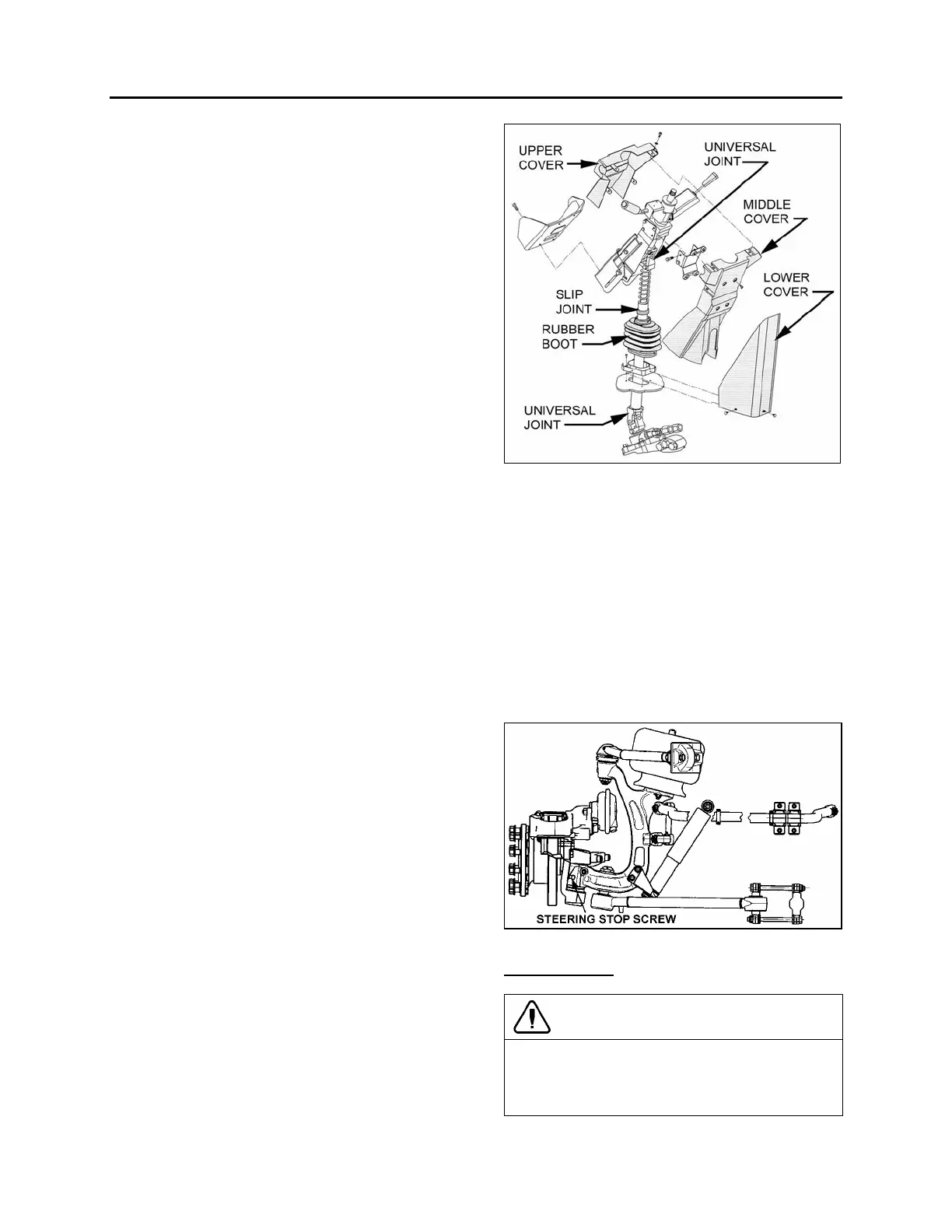
To disassemble the steering column from system,
refer to Figure 4. The steering column has no
lubrication points. The lower steering column
U-joint is easily accessible through the front
service compartment. The upper steering column
U-joint and the steering slip joint are accessible
from the front driver's area. To access these
joints, proceed as follows:
1. From the front driver's compartment area,
remove the three plastic fasteners on steering
column lower cover. Remove the lower cover
(Fig. 4).
2. Unscrew the four retaining screws on
steering column middle cover.
3. Unscrew the four retaining screws fixing
steering column upper cover to middle cover.
Remove the steering column middle and
upper covers.
4. Position the steering wheel in order to gain
access to the joints.
FIGURE 4: STEERING COLUMN
14040
9. TURNING ANGLE ADJUSTMENT
The maximum turning angle is set through two (2)
steering stop screws installed on the knuckles.
Steering stop screws are factory adjusted to
accommodate the chassis design, and therefore,
do not require adjustment on new vehicles.
However, these should be checked and adjusted
if necessary, any time a steering system
component is repaired, disassembled or adjusted.
Refer to section 16 "Suspension" under heading
‘’2.2 ‘’Steering Linkage Adjustment".
FIGURE 5: STEERING STOP SCREW 14063
Hydraulic Stop
CAUTION
Reduce or shut off the power steering hydraulic
pressure before the boss on the knuckle
touches the stop screw. If not, the components
of the front end will be damaged (refer to "ZF-
 Loading...


