Section 6: ELECTRICAL
PA1553
48
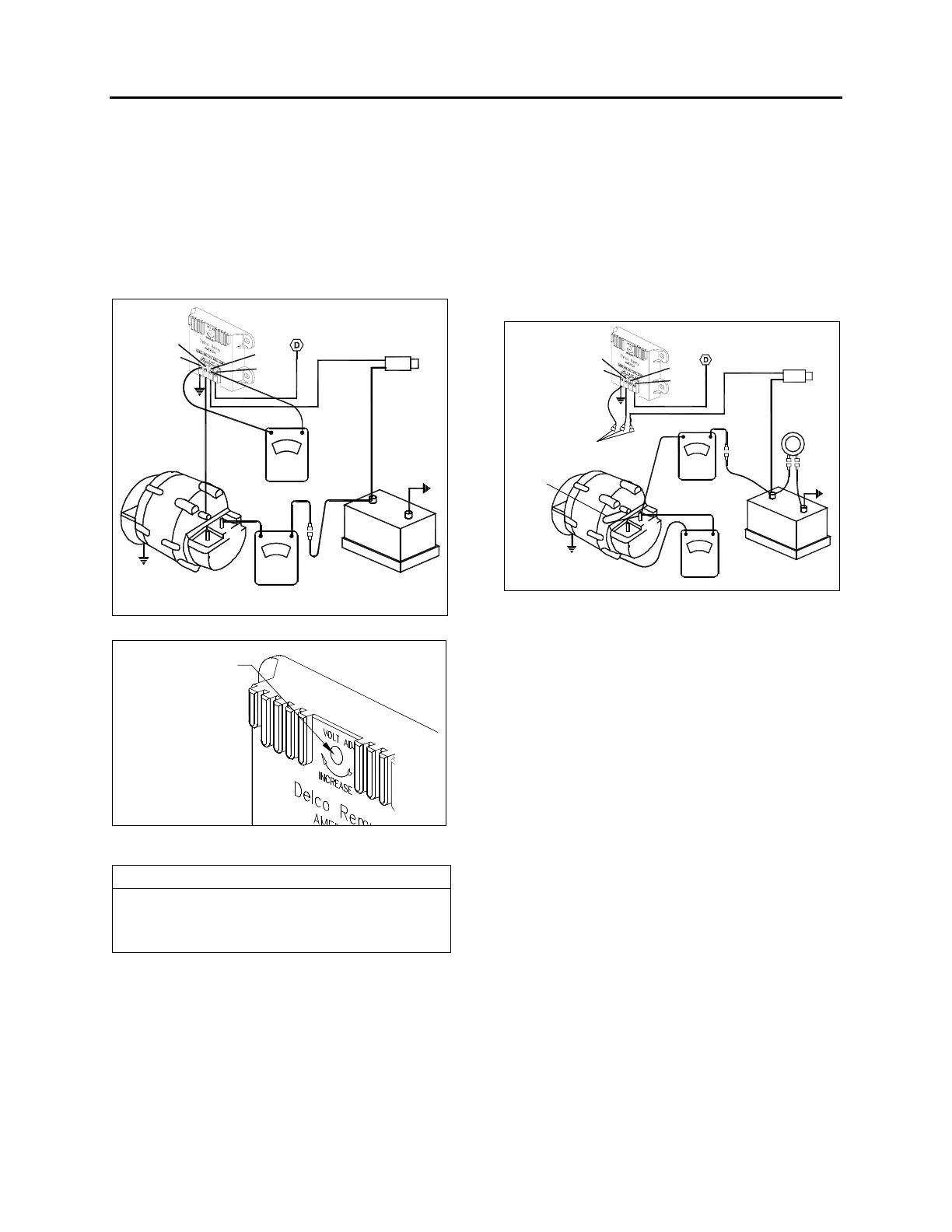
3. Note the voltage setting. It should be steady
at 27.5 volts.
4. If not, the desired setting can be obtained by
removing the plug from the voltage regulator
cover and slightly turning the adjusting
screw inside the regulator. Turn the
adjusting screw clockwise to increase the
voltage setting or counterclockwise to
decrease it. See figure 35 for details.
F
DC
TEST
AMMETER
VOLTMETER
BATTERY
REGULATOR
ALTERNATOR
SWITCH
BATTERY
JUNCTION BOX
GND
FLD
BAT
IGN
FIGURE 34: REGULATOR VOLTAGE SETTING 06416
Adjusment Screw
FIGURE 35: ADJUSTING REGULATOR VOLTAGE
SETTING
06418
NOTE
If regulator voltage cannot be adjusted to the
specified setting, remove the regulator and
repair or replace it as necessary.
8.1.1 Undercharged Battery
If the voltage setting is steady and reasonably
close to the specified value and the battery is
undercharged, raise the setting by 0.3 volt, then
check for an improved battery condition over a
minimum service period of 48 hours. If the
voltage cannot be adjusted to the desired value,
the alternator should be checked as follows:
1. Stop alternator, turn off all accessories and
disconnect battery ground cable.
2. Disconnect all leads from the regulator and
from the alternator field. Do not allow leads
to touch ground.
3. Connect a voltmeter and an ammeter in the
circuit at the alternator "DC" terminal.
4. Connect a jumper lead from the alternator
"DC" terminal to the alternator field terminal.
F
DC
TEST AMMETER
VOLTMETER
BATTERY
REGULATOR
ALTERNATOR
SWITCH
BATTERY
JUNCTION BOX
GND
FLD
BAT
IGN
CARBON
PILE
JUMPER
LEAD
LEADS
DISCONNECTED
FIGURE 36: REGULATOR VOLTAGE TEST
(UNDERCHARGED BATTERY)
06417
5. Connect a carbon pile resistor load across
the battery. Turn to the "Off" position.
6. See figure 36 for wiring connections.
7. Reconnect battery ground cable
8. Turn on all vehicle accessories.
9. Operate alternator and adjust carbon pile
resistor load as required to check for rated
output as given in Delco-Remy Service
Bulletin 1G-187 or 1G-188.
10. Check the alternator field winding as follows:
Disconnect the lead from the field terminal
and connect an ohmmeter from the field
terminal to ground. A resistance reading
above normal indicates an open field, and a
resistance reading less than normal
indicates a shorted or grounded field. The
normal resistance can be calculated by
dividing the voltage by the field current
published in Delco-Remy Service Bulletin
1G-186, 1G-187, or 1G-188. The normal
resistance value should be at or near
midscale on the ohmmeter for accuracy. An
alternate method of checking is to connect a
battery of specified voltage and an ammeter
in series with the field winding, and compare
 Loading...


