Section 22: HEATING AND AIR CONDITIONING
PA1553
39
For complete system recovery, any of the High
and Low service ports can be used (Refer to fig.
38, 42 & 43). Energize liquid refrigerant solenoid
valve and measure the quantity of oil recovered.
For the compressor only, use the service valve
port and close the valves. The service valves
open permits full flow of refrigerant to service
port. Service valve closed permits flow of
refrigerant from compressor to service port.
FIGURE 38: SMALL HVAC SYSTEM FRONT
COMPONENTS
10.3.5 Compressor Handling
Do not strike, drop or turn the compressor
upside down. If the compressor is knocked over
or turned upside down, rotate the compressor’s
magnetic clutch 5 to 6 times by hand to circulate
the oil which has settled in the cylinder. Sudden
rotation with oil in the cylinder can cause valve
damage and adversely affect durability.
10.4 COMPRESSOR REMOVAL
10.4.1 When the compressor is operational
* Perform the “OIL RETURN OPERATION”
(Refer to paragraph 10.9).
10.4.2 When the compressor is inoperable
* Perform the “Refrigerant Recovery”
operation (Refer to paragraph 10.3.4).
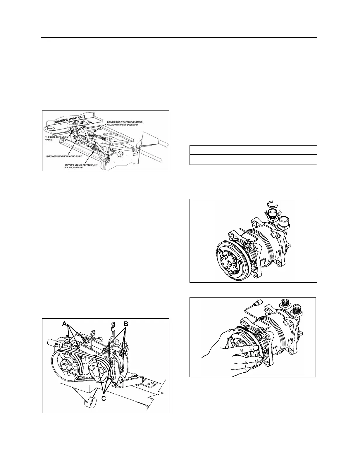
FIGURE 39: COMPRESSOR REMOVAL OR
INSTALLATION
22285
* Slacken bolts A (Refer to figure 39).
* Remove bolts B & C (Refer to figure 39).
* Remove the compressor.
10.5 INSTALLATION PRECAUTIONS
The new compressor is filled with the specified
quantity of compressor oil and nitrogen gas (N²).
When mounting the compressor on the vehicle,
take the following steps:
* Loosen the discharge side connector’s cap
and gently release N² from compressor
(Refer to figure 40).
NOTE
Take care not to let the oil escape.
* Slowly rotate the compressor’s magnetic
clutch several times by hand to distribute the
oil which has settled in the cylinders (Refer
to figure 41).
FIGURE 40: LOOSENING THE DISCHARGE SIDE
CONNECTOR'S CAP
FIGURE 41: ROTATING MAGNETIC CLUTCH
* When using the old compressor in the
system, the compressor should be installed
after changing the oil.
 Loading...


