Section 12: BRAKE AND AIR SYSTEM
PA1553
27
Maintenance
No specific maintenance is required for the
solenoid control valve.
29.2.3 Sensors
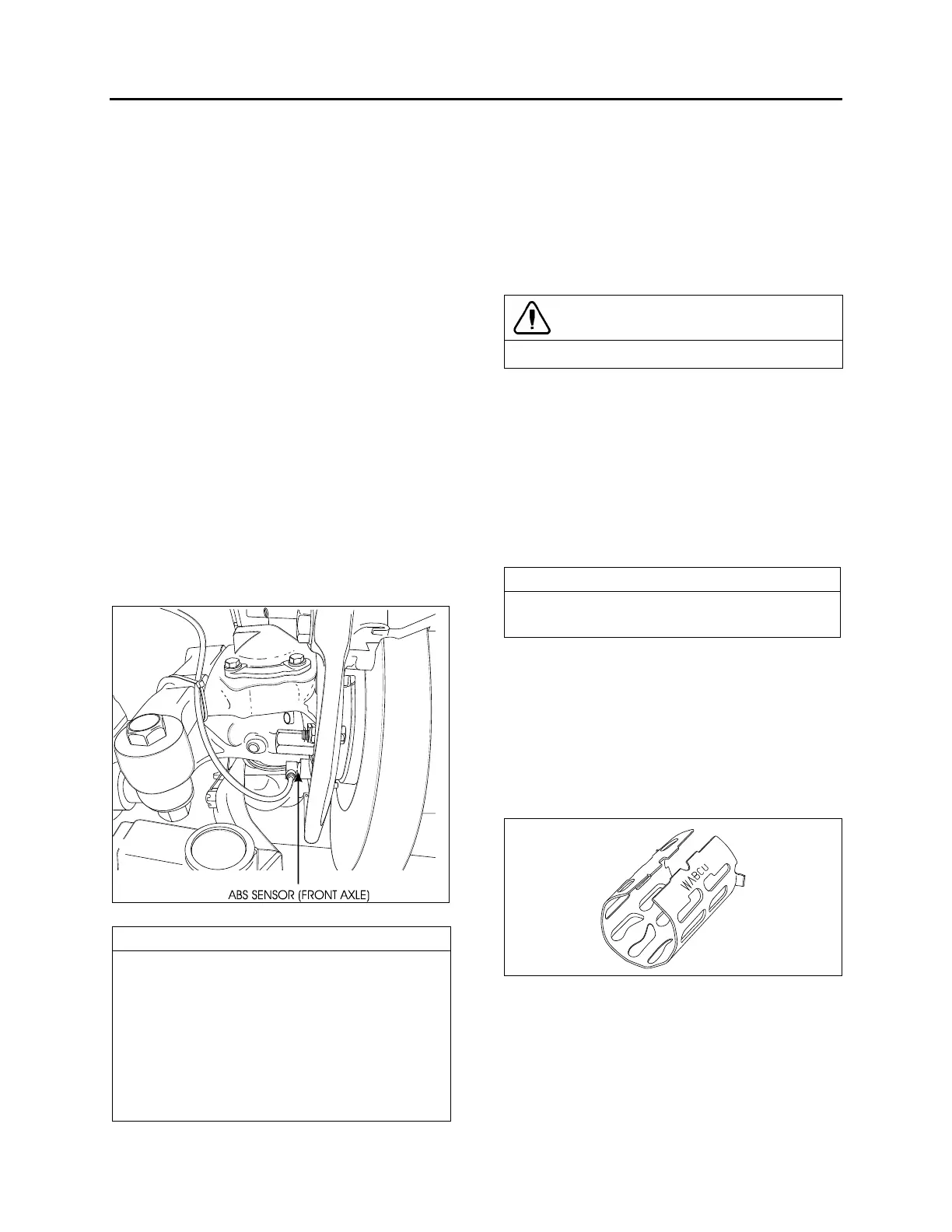
The sensors are mounted on the front and drive
axle wheel hubs (Fig. 44). The inductive sensors
consist essentially of a permanent magnet with a
round pole pin and a coil. The rotation of the
toothed wheel alters the magnetic flux picked up
by the coil, producing an alternating voltage, the
frequency of which is proportional to wheel
speed. When wheel speed decreases, magnetic
flux decreases proportionately. Consequently,
the electronic control unit will command the
solenoid control valve to decrease the pressure
at the corresponding brake chamber.
Maintenance
No specific maintenance is required for sensors,
except if the sensors have to be removed for
axle servicing. In such a case, sensors should
be lubricated with special grease (Prévost
#680460) before reinstallation. Refer to
paragraph “Sensor Installation” for details.
FIGURE 44: ABS SENSOR LOCATION 12153
NOTE
The resistance value, when sensors are
checked as a unit, must be equal to 1,75 k
ohms. To check the sensors for proper output
voltage after the sensors and toothed wheels
have been assembled to the axle, connect a
suitable AC voltmeter across the output
terminals. With the hubs rotating at 30 rpm,
the output voltages should read from 50 to
1999 mV to be acceptable.
29.2.4 Sensor Installation
The following procedure deals with sensor
installation on the axle wheel hubs. Read
procedure carefully before reinstalling a sensor,
as its installation must comply with operational
tolerances and specifications.
1. Apply recommended lubricant (Prévost
#680460) to spring clip and sensor.
CAUTION
Use only this type of grease on the sensors.
2. Insert spring clip in the holder on hub. Make
sure the spring clip tabs are on the inboard
side of the vehicle. Push in until the clip
stops.
3. Push the sensor completely inside the
spring clip until it is in contact with the tooth
wheel. Ensure mounting is rigid, as it is an
important criterion for adequate sensor
operation.
NOTE
This installation should be of the "press fit"
type.
29.2.5 Spring clip
The spring clip retains the sensor in its mounting
bracket close to the toothed pulse wheel. The
gap between the sensor end and teeth is set
automatically by pushing the sensor in the clip
hard up against the tooth wheel, and the latter
knocks back the sensor to its adjusted position
(Fig. 45).
FIGURE 45: SPRING CLIP 12161
Maintenance
The spring clip requires no specific
maintenance.
 Loading...


