Section 22: HEATING AND AIR CONDITIONING
PA1553
22
NOTE
Both belts must always be replaced
simultaneously to ensure an equal distribution
of load on each of them.
NOTE
For proper operation of the air bellows, adjust
the upper tensioning bracket to provide a ¼
inch (7 mm) gap between stopper and bracket
with the pneumatic system under normal
pressure and the air pressure regulator set as
per paragraph #3 (Fig. 19).
FIGURE 19: BELT TENSIONER 01059
9.1.2 Pulley Alignment
In order to avoid skipping, disengagement and a
premature wear of compressor belt, it is
necessary to align compressor pulley with the
crankshaft pulley. Before performing the
following procedure, release air from belt
tensioners by means of the air pressure
releasing valve. After completing these
procedures reset belt tensioner air pressure
regulator to 45 psi (310 kPa).
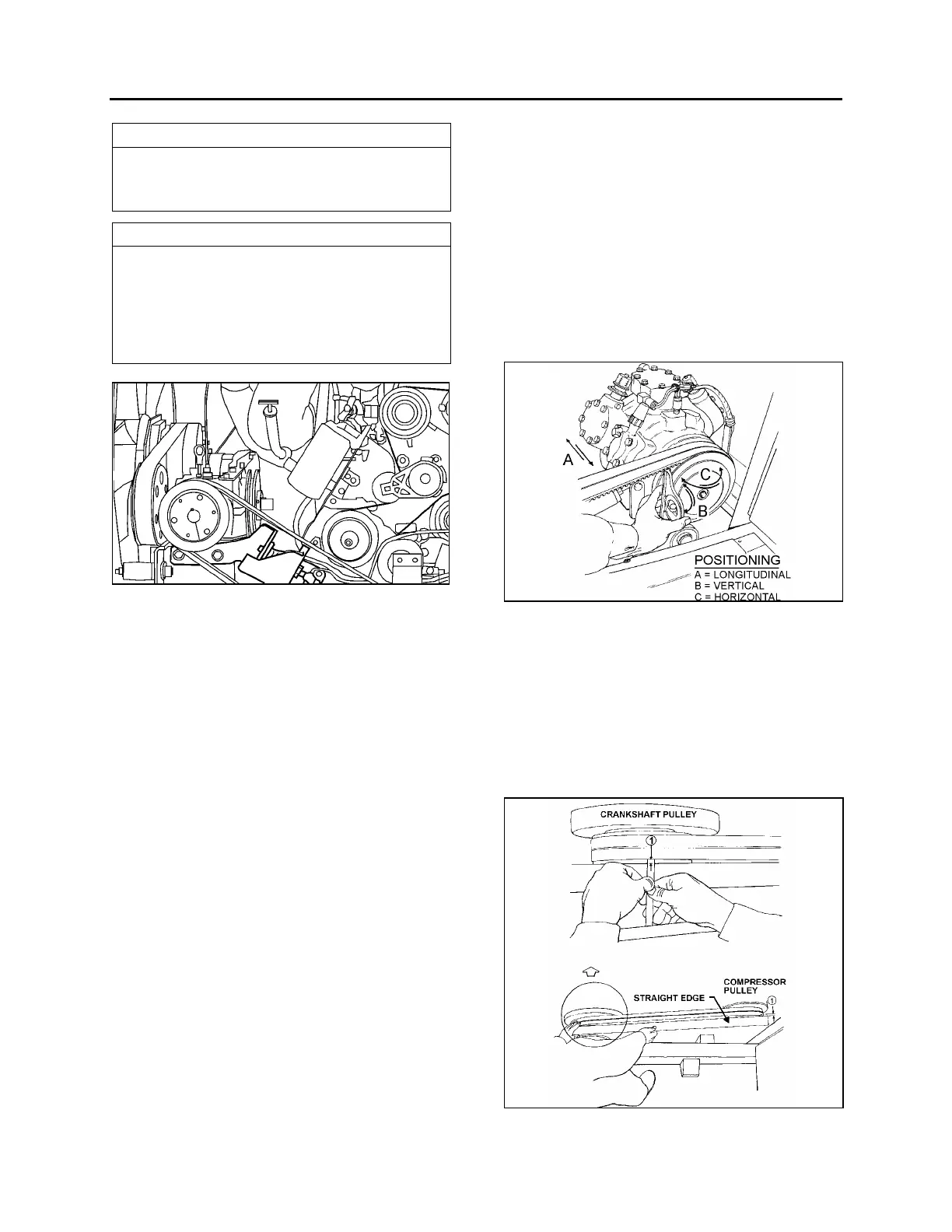
9.1.3 Longitudinal Compressor Alignment
1. Rest an extremity of a straight edge of
approximately 46 inches (117 cm) against
the upper part of the outer face of crankshaft
pulley, positioning the other end close to the
compressor clutch pulley (Figs. 20 & 21).
2. Check the distance between each extremity
of straight edge (1. Fig. 21) and the first
drive belt. If they are different, loosen the
compressor support bolts and with a
hammer, knock support to slide it in order to
obtain the same distance; then tighten bolts.
9.1.4 Horizontal Compressor Alignment
1. Rest an extremity of the straight edge
against the upper part of the outer face of
compressor pulley, positioning the other end
close to the crankshaft pulley.
2. Check the distance between each extremity
of straight edge (1, Fig. 21) and drive belt. If
they are different, loosen the pillow block
compressor bolts and with a hammer, knock
compressor pillow block to slide it, in order
to obtain the same distance; then tighten
bolts.
FIGURE 20: COMPRESSOR ALIGNMENT 22072
9.1.5 Vertical Compressor Alignment
Rest a short "angle and level indicator" on the
outer side face of the crankshaft pulley, adjust
the level indicator inclination at 0
o
and check if
the compressor pulley is at same angle (Figs. 20
& 21). If it is not the same, shim under the
appropriate pillow block in order to obtain the
correct angle.
FIGURE 21: COMPRESSOR ALIGNMENT 22040
 Loading...


