Section 6: ELECTRICAL
PA1553
55
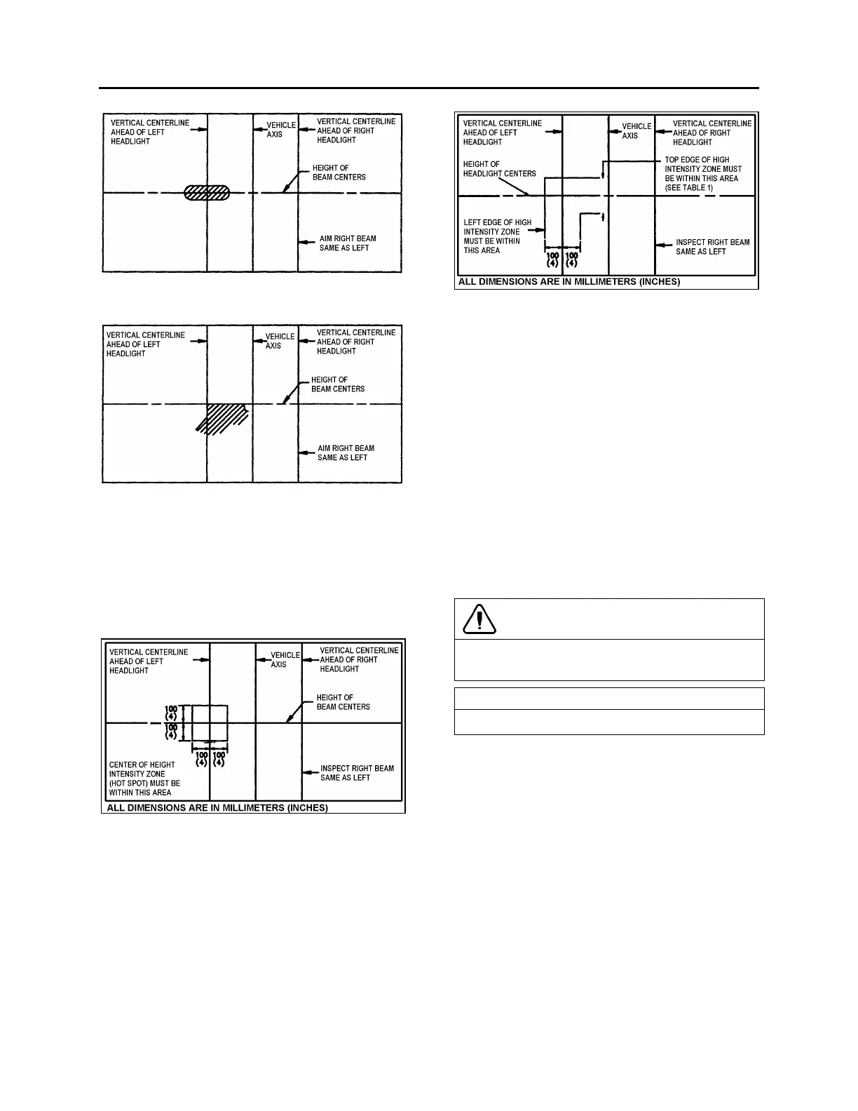
FIGURE 50: HIGH-INTENSITY ZONE (SHADED AREA) OF
A PROPERLY AIMED UPPER BEAM ON THE AIMING
SCREEN 7.6 M (25FT) IN FRONT OF VEHICLE
06503
FIGURE 51: HIGH-INTENSITY ZONE (SHADED AREA) OF
A PROPERLY AIMED LOWER BEAM ON THE AIMING
SCREEN 7.6 M (25FT) IN FRONT OF VEHICLE
06504
7. The inspection limits for high-beam
headlights shall be with the center of the
high-intensity zone from 10 cm (4 in) up to
10 cm (4 in) down; and, from 10 cm (4 in)
left to 10 cm (4 in) right on a screen at 7.6 m
(25 ft) (Fig.52).
FIGURE 52: AIM INSPECTION LIMITS FOR UPPER-BEAM
HEADLIGHTS
06505
8. The inspection limits in the vertical direction
for low-beam headlights or the low beam of
a dual-beam headlight, shall be as
described in Table 1. In the horizontal
direction, the left edge of the high-intensity
zone shall be located from 10 cm (4 in) left
to 10 cm (4 in) right of the vertical centerline
of the beam. The viewing screen shall be
located 7.6 m (25 ft) in front of the vehicle
(Fig. 53).
FIGURE 53: AIM INSPECTION LIMITS FOR LOWER-
BEAM HEADLIGHTS
06506
12.1.4 Sealed-Beam Unit
Bulb Removal and Replacement
1. Pull the release handle located inside the
front service compartment to tilt down the
entire bumper assembly.
2. Remove the headlight screw fixing the
headlight assembly, then tilt headlight
assembly down (Fig. 40 and 41).
3. Remove connector from headlight bulb.
4. Remove the bulb by pushing and rotating it
out of the socket.
5. Install the new bulb by reversing the
previous procedure.
CAUTION
During this step, avoid contacting the bulb with
the fingers not to alter the bulb life.
NOTE
Do not disrupt headlight adjustment screws.
Module Replacement
1. Pull the release handle located inside the
front service compartment to tilt down the
entire bumper assembly.
2. Remove the headlight screw fixing the
headlight assembly, then tilt headlight
assembly down (Fig. 40 and 41).
3. Remove connector from headlight bulb.
4. Unfasten three metal clips attaching
headlight unit to support.
5. Install new module and fasten metal clips.
6. Install wiring connector on back of new
sealed beam unit.
 Loading...


