Repair and Testing Instructions for T1 Page 26
Alternator 0120 689 552 Edition 001
All rights rest with Robert Bosch Corp, including patent rights. All rights of use of reproduction and publication rest with R. B. Corp.
UA/ASV 04.12.98 T1ALTFinal.DOC
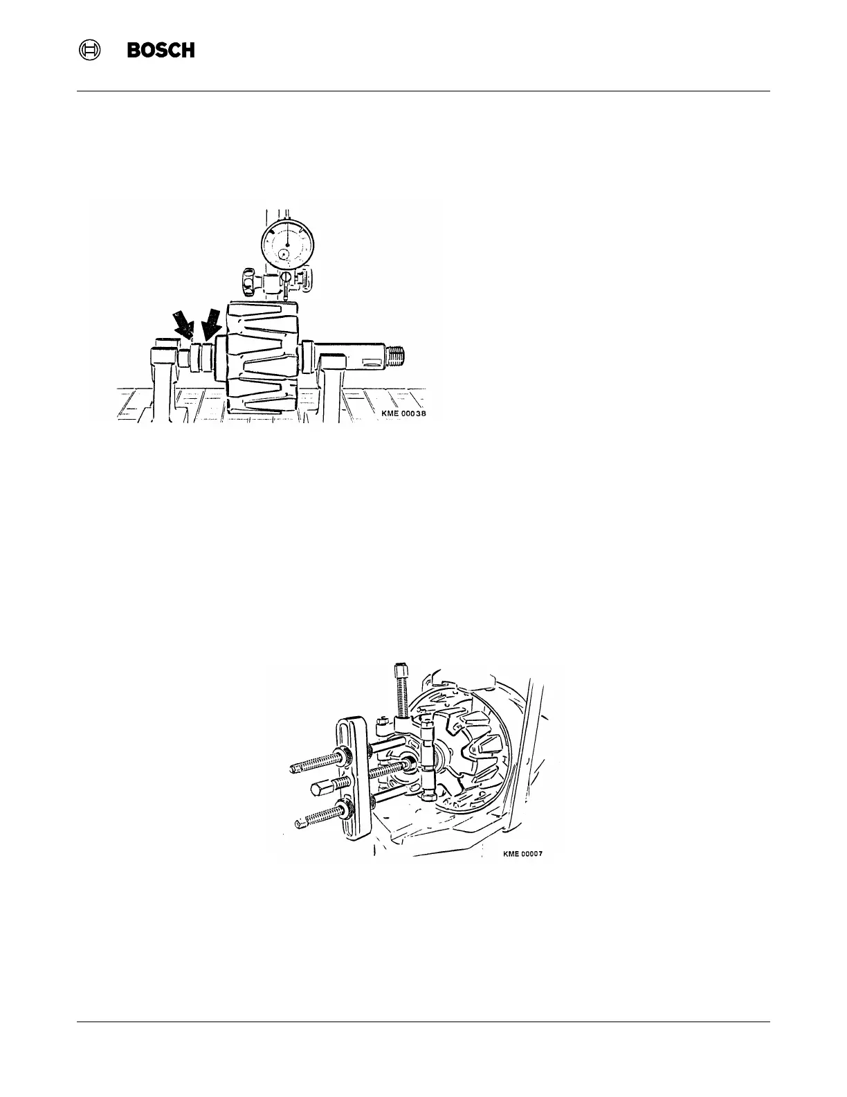
4. Position dial indicator (Magnetic Base T-M 1 (Bosch Number 4 851 601 124) and Dial Indicator EFAW 7
(Bosch Number 1 687 233 011)) to measure the concentricity of the rotor at:: (Figure 23)
a. Outer diameter of rotor, maximum run-out 0.05 mm (0.002 in). If the run-out of the rotor exceeds the
maximum, the rotor must be replaced.
b. Each collector ring, maximum run-out 0.03 mm (0.0012 in). If the run-out exceeds the maximum, the
collector rings can be machined down to a minimum of 31.5 mm (1.240 in) diameter. If the required
machining causes the collector ring diameter to drop below the minimum dimension, the collector ring(s)
must be replaced.
9.16 Collector Ring Replacement
1. Before the collector rings can be removed, the spacer ring from the end of the rotor must be removed.
Refer to Section 9.14 "Removal of Inner Bearing Race from Rotor."
2. Unsolder the rotor leads from each collector ring.
3. With a universal bearing puller, remove each collector ring one at a time from the rotor. (Figure 24)
Figure 24 Collector Ring Removal
Figure 23 Rotor Concentricity Measurement
 Loading...


