Section 12: BRAKE AND AIR SYSTEM
PA1553
10
2. Access this valve by tearing out the finishing
panel, which holds the controls in place
(Fig. 9).
3. Disconnect the air tubes.
4. Remove the retaining screws.
5. Service or replace the valve.
6. Installation is the reverse of removal.
12. FLIP-FLOP CONTROL VALVE (TW-1)
A flip-flop control valve mounted on the L.H.
lateral console is provided to unload and to lift
tag axle air springs. It is a manually operated
"on-off" valve. Maintenance and repair
information on this valve is supplied in the
applicable booklet annexed to this section under
reference number SD-03-3602.
FIGURE 10: TW-1 12138
13. DUAL BRAKE APPLICATION VALVE
(E-10P)
The E-10P dual brake valve is a floor mounted,
foot-operated type brake valve with two separate
supply and delivery circuits. This valve is located
in the front service compartment (Fig. 11).
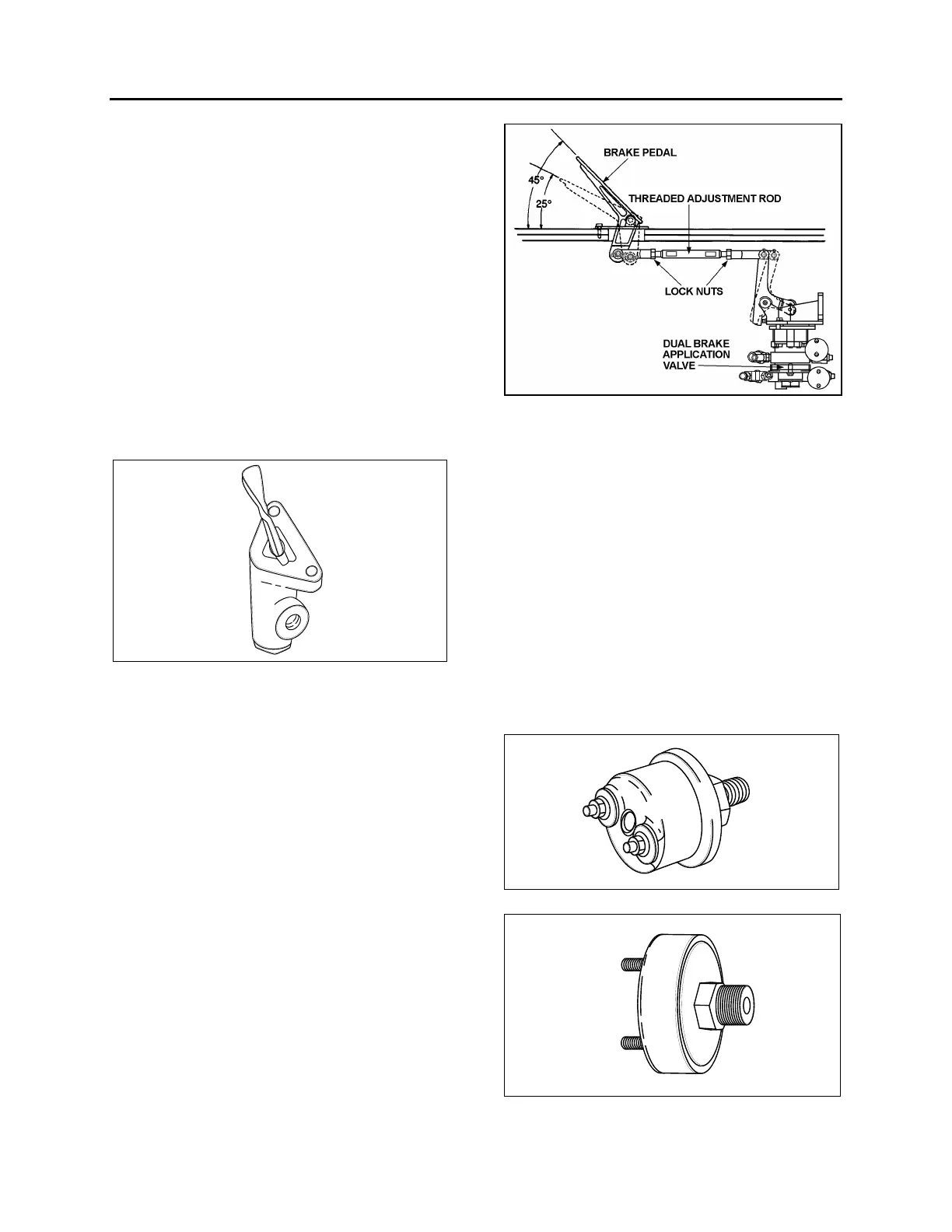
13.1 BRAKE PEDAL ADJUSTMENT
After brake pedal replacement or repair, adjust
the pedal to its proper position according to the
following procedure:
1. Replace the linkage, loosen threaded rod
lock nuts and screw or unscrew the
threaded adjustment rod in order to obtain a
45
o
brake pedal inclination (Fig. 11).
2. Tighten threaded rod lock nuts.
13.1.1 Maintenance
Maintenance and repair information on the E-10P
dual brake application valve is supplied in the
applicable booklet annexed to this section under
reference number SD-03-830.
FIGURE 11: BRAKE PEDAL ADJUSTMENT 12208
14. STOPLIGHT SWITCHES
Two electro-pneumatic stoplight switches are
mounted on the dual brake application valve (E-
12). The upper one is used for the primary air
circuit while the lower one is used for the
secondary air circuit. Both switches are
connected in parallel and have the same
purpose, i.e. completing the electrical circuit and
lighting the stoplights when a brake application
is made. The upper switch (AC Delco) is
designed to close its contact between 2 psi and
4 psi (14 kPa to 28 kPa) (Fig. 12), while the
lower one (Bendix, SL-5) closes its contact at 4
psi (28 kPa) (Fig. 13). The switches are not
serviceable items; if found defective, the
complete unit must be replaced.
FIGURE 12: DELCO SWITCH 12139
FIGURE 13: BENDIX SWITCH 12140
 Loading...


