Section 26: XLII SLIDE-OUT
PA1553
28
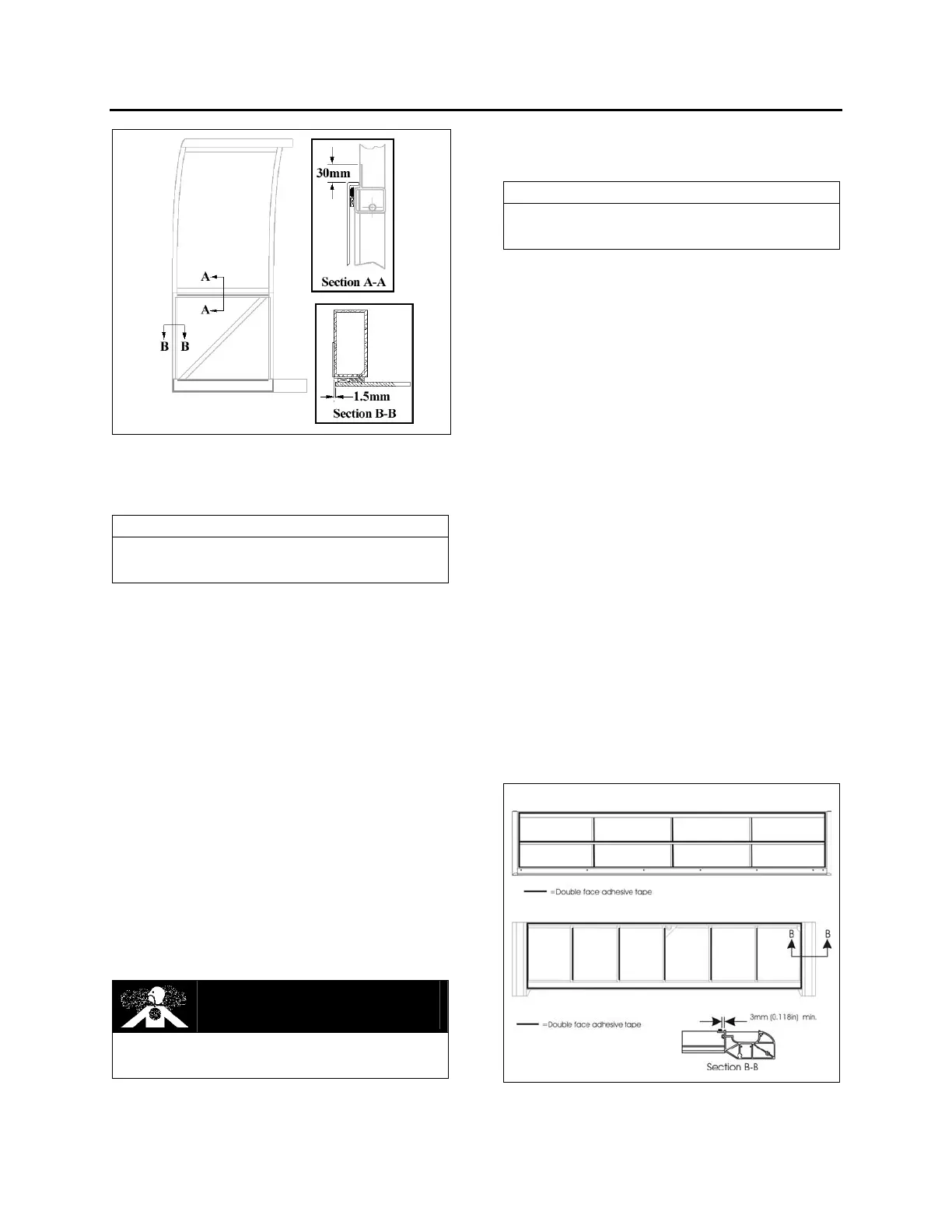
FIGURE 44 : SIDE PANEL INSTALLATION
16.5 TOP AND BOTTOM PANEL
REMOVAL
NOTE
The top and bottom panels are made of
aluminum sheets.
1. Remove the slide-out (according to the
Slide-Out Removal Procedure. Ask to your
Prevost service representative).
2. Insert a flat screwdriver between the panel
and the slide-out structure, and unstick the
panel from the structure.
3. Use C-clamp to peel the panel from the
slide-out structure.
4. Check where adhesive, sealant and double
face adhesive tape are on the structure and
the panel back side, in order to be able to
stick the new panel in the same way.
5. Check the tape width and use same width
tape when installing new panels.
6. Use a heat gun and putty knife to remove
the dried off adhesive and tape residue from
the structure.
DANGER
Because of the adhesive toxicity, never use a
buffer or other sanding method to remove it.
16.6 TOP AND BOTTOM PANEL
INSTALLATION
NOTE
The top and bottom panels are made of
aluminum sheets and need aluminum rivet.
For surface cleaning, preparation, panel
installation and products needed, refer to the
MTH side panel installation procedure described
in section 18: BODY.
1. Protect adjacent surfaces with appropriate
material.
2. Refer to FIGURE 45 for 1/16x1/4 double
face adhesive tape location on structure;
3. Apply Sika 206 G+P on panel as shown in
FIGURE 46;
4. Apply Sika Tack+Booster (triangular bead:
9mm width X 6mm high) has shown in
FIGURE 47 and glue panel in place as
shown in figure
48 & figure 49 ;
5. Exert pressure and let dry for at least 90
minutes;
6. Smooth down the joint and remove glue in
excess;
7. After drying, apply Sika 252 as a finishing
joint;
8. Smooth down the joint.
9. Refer to section 16.11 for the finishing joint
application procedure.
Top structure
Bottom structure
FIGURE 45 : TOP AND BOTTOM PANEL INSTALLATION -
DOUBLE FACE ADHESIVE TAPE APPLICATION
 Loading...


