Section 06: ELECTRICAL
PA1553
12
F66 Power Fan Clutch F90 Spare
F67 24VI A54 F91 Spare
F68
F69
F70
24VI A54
24VI R8
24 VI Customer
F96
F98
F99
Spare
Spare
Spare
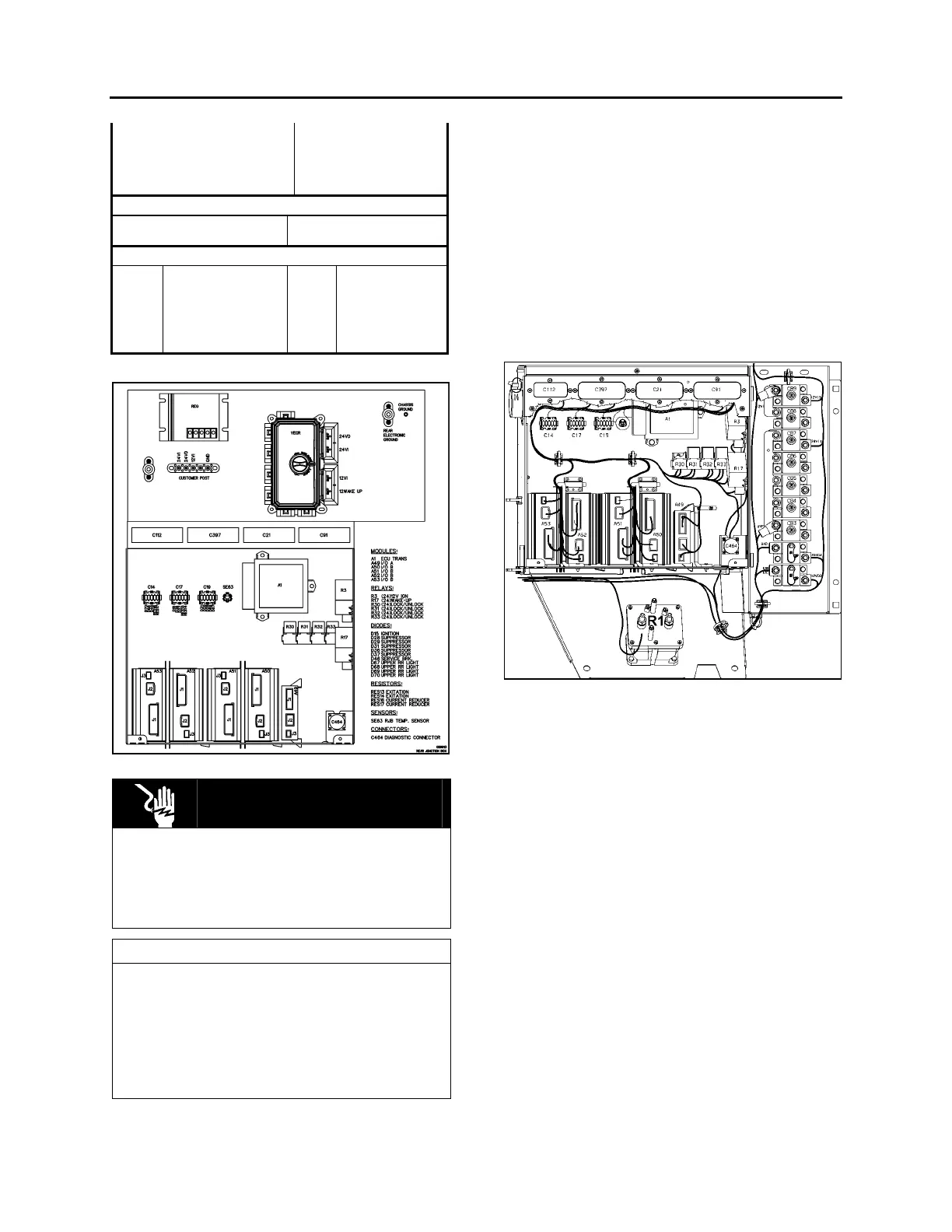
Resistors
RES13 Excitation RES16 Current Reducer
RES14 Excitation RES17 Current Reducer
Diodes
D15 Ignition D46 Service Brakes
D28 Suppression D67 Upper Rear Light
D29 Suppression D68 Upper Rear Light
D31 Suppression D69 Upper Rear Light
D36 Suppression D70 Upper Rear Light
D37 Suppression
FIGURE 6: REAR JUNCTION BOX 06508
DANGER
During repair or maintenance periods, set
ignition key switch to the "OFF" position in
order to avoid personal injury. This ensures
that power from the batteries is automatically
cut off.
NOTE
When ignition key switch is set to the "OFF"
position, the electrical supply from the
batteries is cut off, with the exception of the
Fire Detection System, the Engine &
Transmission Electronic Controls, the Auxiliary
Heating System, the Battery Equalizers and
the Digital Clock.
2.3 CIRCUIT BREAKERS
All manually-resettable circuit breakers are
located in the engine compartment R.H. side
area. An identification decal is affixed on the
inside face of the door.
MTH W0, WE and W5 may be equipped with
nine (9) main breakers; six (5) of which are
standard (CB1, CB2, CB3, CB7 & CB9). Three
(3) are supplied only on vehicles equipped with
central A/C system (CB4, CB5 & CB8); and one
(1) is supplied only on vehicles equipped with
slide-out (CB6).
FIGURE 7: REAR JUNCTION BOX & CIRCUIT BREAKER
PANEL
On all vehicles, breakers CB1 to CB9 are
installed on circuit breaker panel in engine
compartment R.H. side area (Fig. 7). They are
accessible through engine R.H. side door and
can be identified as follows:
1. Distribution (CB1) 150 A - 12 volts;
2. Distribution (CB2) 50 A - 24 volts;
3. Front Distribution (CB3) 70 A - 24 volts;
4. Distribution (CB7) 60 A - 24 volts;
5. Distribution (CB9) 70 A - 12 volts;
On all vehicles equipped with central A/C,
breakers CB4, CB5 and CB8 are installed on
breaker panel in engine compartment R.H. side
area (Fig. 7). They are accessible through
engine R.H. side door and are identified as
follows:
1. HVAC - Evaporator (CB4) 90 A - 24 volts;
2. HVAC – Condenser (CB5) 70 A - 24 volts;
3. HVAC - Condenser (CB8) 40 A - 12 volts.
 Loading...


