Section 11: REAR AXLES
PA1553
5
1.7 GEAR SET IDENTIFICATION
Gear set identification is covered under
applicable heading in Meritor's "MAINTENANCE
MANUAL NO. 5", annexed to this section.
1.8 ADJUSTMENTS
Adjustments are covered under applicable
headings in Meritor's "MAINTENANCE MANUAL
NO. 5", annexed to this section.
1.9 FASTENER TORQUE CHART
A differential fastener torque chart is provided in
Meritor's "MAINTENANCE MANUAL NO. 5",
annexed to this section.
1.10 TIRE MATCHING
Drive axle tire matching is covered under the
applicable heading in Section 13, "Wheels, Hubs
And Tires" in this manual.
1.11 DRIVE AXLE ALIGNMENT
NOTE
For drive axle alignment specifications, refer to
paragraph 3: ‘’Specifications’’ in this section.
The drive axle alignment consists in aligning the
axle according to the frame. The axle must be
perpendicular to the frame. The alignment is
achieved with the use of shims inserted between
the lower longitudinal radius rod supports and
the frame.
Drive axle alignment is factory set and is not
subject to any change, except if the vehicle has
been damaged by an accident or if there are
requirements for replacement.
If the axle has been removed for repairs or
servicing and if all the parts are reinstalled
exactly in the same place, the axle alignment is
not necessary. However, if the suspension
supports have been replaced or altered,
proceed with the following instructions to verify
or adjust the drive axle alignment.
NOTE
When drive axle alignment is modified, tag
axle alignment must be re-verified.
1.11.1 Procedure
1. Park vehicle on a level surface, then chock
front vehicle wheels.
2. Using two jacking points (which are at least
30 inches [76 cm] apart) on drive axle, raise
the vehicle sufficiently so that wheels can
turn freely at about ½ inch from ground.
Secure in this position with safety stands,
and release parking brake.
3. Install wheel mount sensors on front and
drive axle wheels (fig. 7). Adjust front
wheels according to paragraph: “Front End
Alignment” in Section 16: Suspension.
NOTE
See reference numbers on wheel mount
sensors (fig.7).
NOTE
Select axle specifications in the appropriate
chart
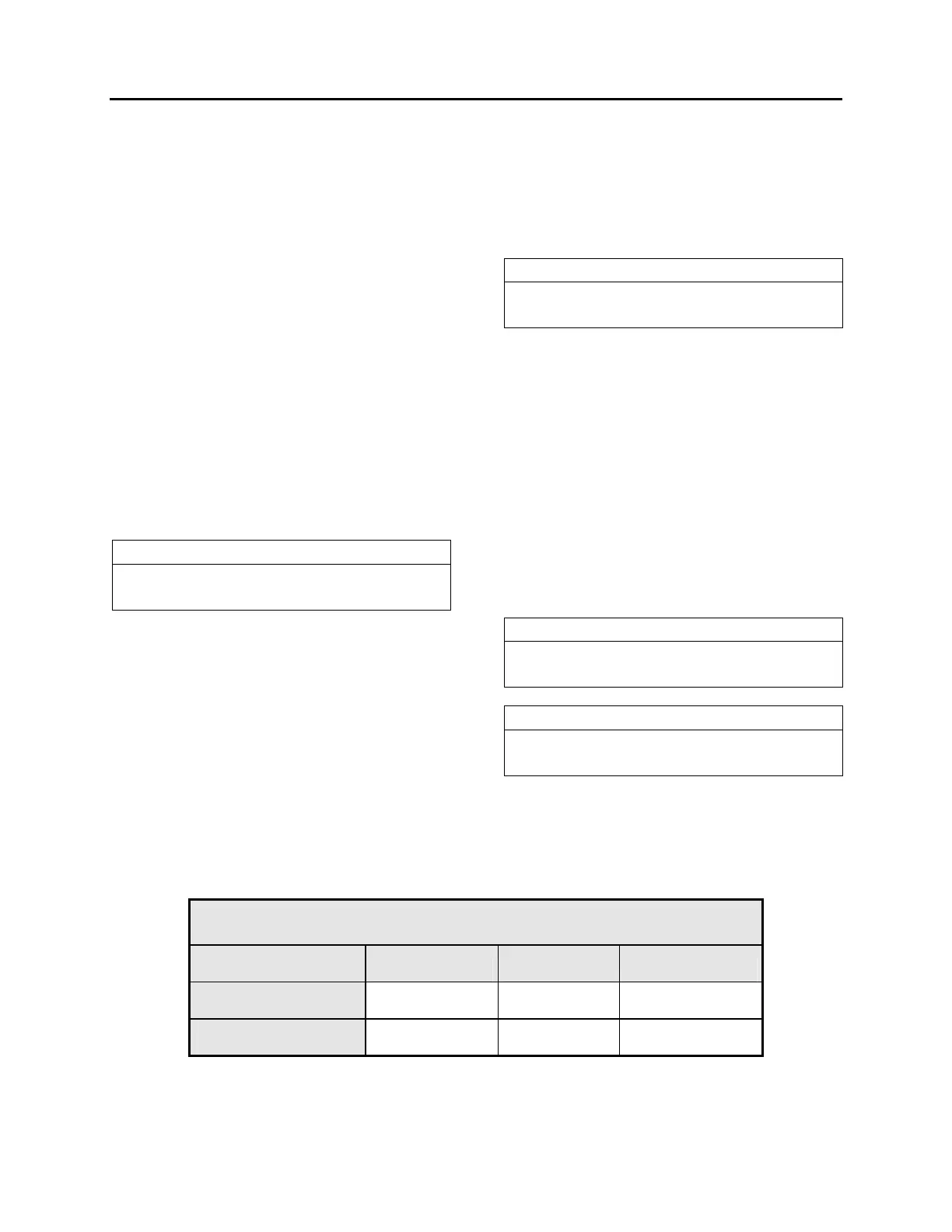
DRIVE AXLE ALIGNMENT
o With the system installed as for front end alignment (fig.7), adjust drive axle according to
specifications' chart below.
DRIVE AXLE
ALL VEHICLES
Alignment / value Minimum value Nominal value Maximum value
Thrust angle (deg.) -0.04 0 0.04
Total Toe (deg.) 0.18 Toe-in 0 0.18 Toe-out
 Loading...


