Section 12: BRAKE AND AIR SYSTEM
PA1553
15
about 5 - 10 times (30 PSI or 2 bar), the
wrench should turn clockwise in small
increments if the adjuster is functioning
correctly (Figs. 24 and 25).
NOTE
With increasing number of applications, the
incremental adjustment will decrease.
c) In case of malfunction, i. e. the pinion or box
wrench:
i) Does not turn.
ii) Turns only with the first application.
iii) Turns forwards then backwards with
every application.
In any of the above cases, the automatic
adjuster has failed and the caliper must be
replaced. In such cases the brakes can be
adjusted manually to run a short distance.
d) Take the box wrench off. Replace the cap
and check for proper sealing.
FIGURE 24: ADJUSTER PINION 12120
FIGURE 25: BOX WRENCH ON ADJUSTER PINION 12118
25.1.3 Roadside Inspection for Knorr/Bendix
Air Disc Brakes
The coach is equipped with air disc brakes and
therefore, cannot be inspected using the
requirements for chamber stroke or visible lining
clearance or lining thickness as specified for
drum brakes. The roadside inspector should use
the following instructions to determine that the
air disc brakes are within proper adjustment and
have sufficient pad wear thickness.
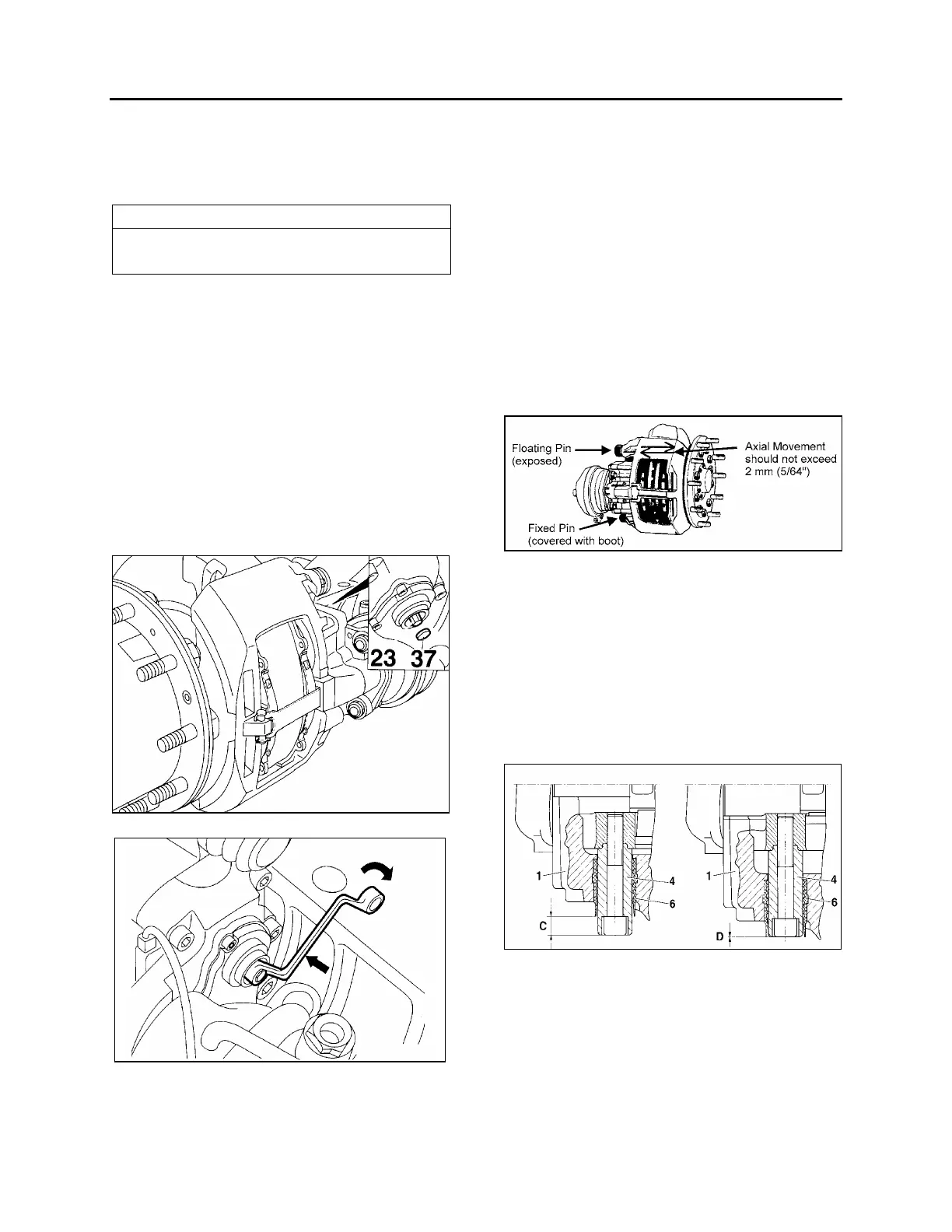
The Knorr/Bendix air disc brake is designed to
move freely, with minimal force, in the axial
direction on the two sliding pins as identified in
figure 26. The movement in the axial direction
should not exceed 2 mm (5/64”).
FIGURE 26: CALIPER AXIAL MOVEMENT 12132
The pad thickness can be seen but would
require removal of the tire and rim. An indicator
of the pad wear condition is available by
inspecting the floating pin location in relation to
the rubber bushing as shown in figure 27. When
pads are in new thickness condition, the pin will
be exposed (C) 19 mm (¾”). When the pads are
worn to replacement conditions, the pin will be
nearly flush to the bushing (D) or within 1 mm
(3/64”) of the edge of the rubber bushing.
FIGURE 27: BRAKE PAD CHECK 12117
25.1.4 Pad Removal
Turn adjuster pinion (23) counterclockwise to
increase pad to rotor clearance (a clicking noise
will be heard). Push caliper toward actuator and
remove pads (12).
 Loading...


