Section 22: HEATING AND AIR CONDITIONING
PA1553
29
safe. A color indication of light blue to light violet
indicates the caution range of moisture level.
For positive protection, the drying of the system
should be continued until the color of the
element turns to deep blue.
The liquid refrigerant is readily visible through
the center opening of the moisture element
where the presence of bubbles indicates a
shortage of refrigerant or restriction in line.
Moisture is one of the main causes of chemical
instability or contamination in air conditioning
systems. If moisture is present, it can corrode
the valves, condenser and evaporator coils,
compressor and other components causing a
malfunction and eventual failure of the system.
Uncontrolled moisture in the system can result
in very expensive multiple component replace-
ments if not corrected at an early stage. The
moisture indicator permits an early detection of
moisture in the system and when corrected by a
desiccant charge, system contamination is
greatly minimized.
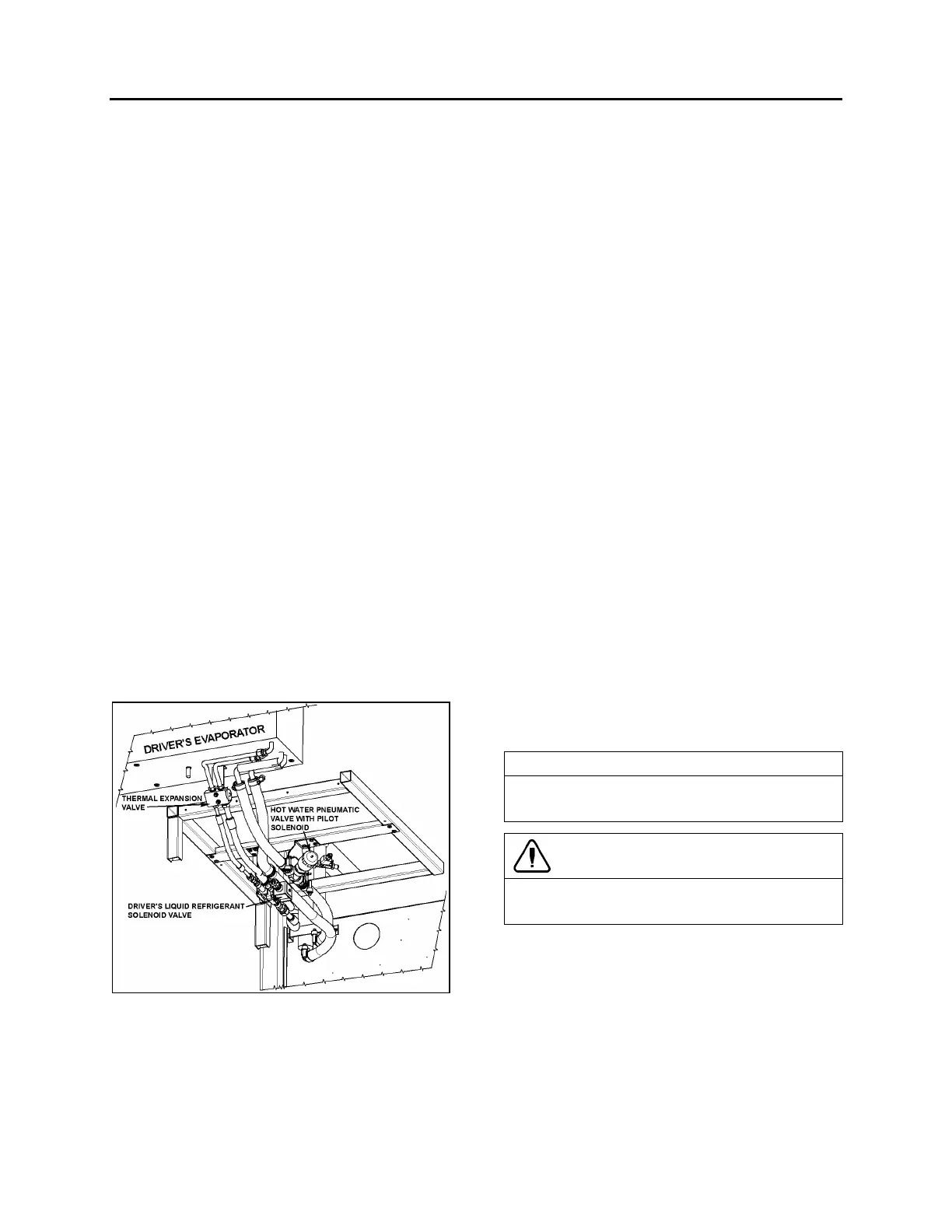
9.7 LIQUID REFRIGERANT SOLENOID
VALVE
The flow of liquid refrigerant to the driver’s and
main evaporators is controlled by a normally-
closed solenoid valve (Refer to fig. 31 & 32).
The driver’s liquid refrigerant solenoid valve is
located on the ceiling of the spare wheel and tire
compartment and is accessible through the
reclining bumper.
FIGURE 32: DRIVER'S LIQUID REFRIGERANT
SOLENOID VALVE
22181
9.7.1 Manual Bypass
This type of solenoid valve is equipped with a
manual operating stem. The 3/16" square stem
located on the bonnet is exposed when the seal
cap is removed. To manually open valve, turn
stem ½ turn counterclockwise. To manually
close valve, turn stem clockwise until tight
against seat. Manual stem must be in closed
position for automatic electric operation.
9.7.2 Coil Replacement
1. Disconnect connector from the coil
connector.
2. Take out the retaining screw at the top of
the coil housing. The entire coil assembly
can then be lifted off the enclosing tube.
3. Place the new coil and yoke assembly on
the enclosing tube. Lay data identification
plate in place.
4. Insert the coil retaining screw, rotate
housing to proper position and tighten screw
securely.
5. Connect connector from coil connector.
9.7.3 Valve Disassembly
1. Remove the coil as stated previously.
2. Pump down the system as stated earlier in
this section.
3. Remove the four socket head screws which
hold the body and bonnet together (Fig. 33).
4. Carefully lift the bonnet assembly off (upper
part of the valve) so that plunger will not fall
out. The diaphragm can now be lifted out.
NOTE
The above procedure must be followed before
brazing solder-type bodies into the line.
CAUTION
Be careful not to damage the machined faces
while the valve is apart.
9.7.4 Valve Reassembly
1. Place the diaphragm in the body with the
pilot port extension up.
2. Hold the plunger with the synthetic seat
against the pilot port.
3. Make sure the bonnet O-rings are in place.
Lower the bonnet assembly over the
plunger, making sure that the locating
 Loading...


