Section 26: XLII SLIDE-OUT
PA1553
14
8 JAW COUPLING
8.1 MAINTENANCE
Inspect the jaw couplings to check if there is
backlash between the key and the keyway. Also,
check the spider condition. Check that the
clamping screws are tight.
8.2 REPLACEMENT &
ADJUSTMENT
1. The slide-out must be retracted.
2. Disengage the jaw coupling: loosen the
clamping screw on each clamping hub. If
required, rotate the motor shaft extension as
described in the manual override procedure
(section 18) to get to the clamping screws.
3. Separate both clamping hubs.
NOTE
It may be necessary to loosen the blue flange
bearings to move the shaft out of the way.
4. Clean and degrease the hub bore and the
shaft.
5. Push the new clamping hubs onto the shaft
(pinion side).
6. Install a clamping hub on one of the gearbox
shaft (opposite side of gearbox mounting
bolts) flush with the shaft extremity (FIGURE
19). Tighten the clamping screw to a torque
of 18 lbf-ft.
7. Install the second clamping hub on the
gearbox shaft. Position the clamping hubs
so that they are flush with the shafts
extremity (see FIGURE 19).
FIGURE 19: CLAMPING HUB POSITION ON GEARBOX
SHAFT
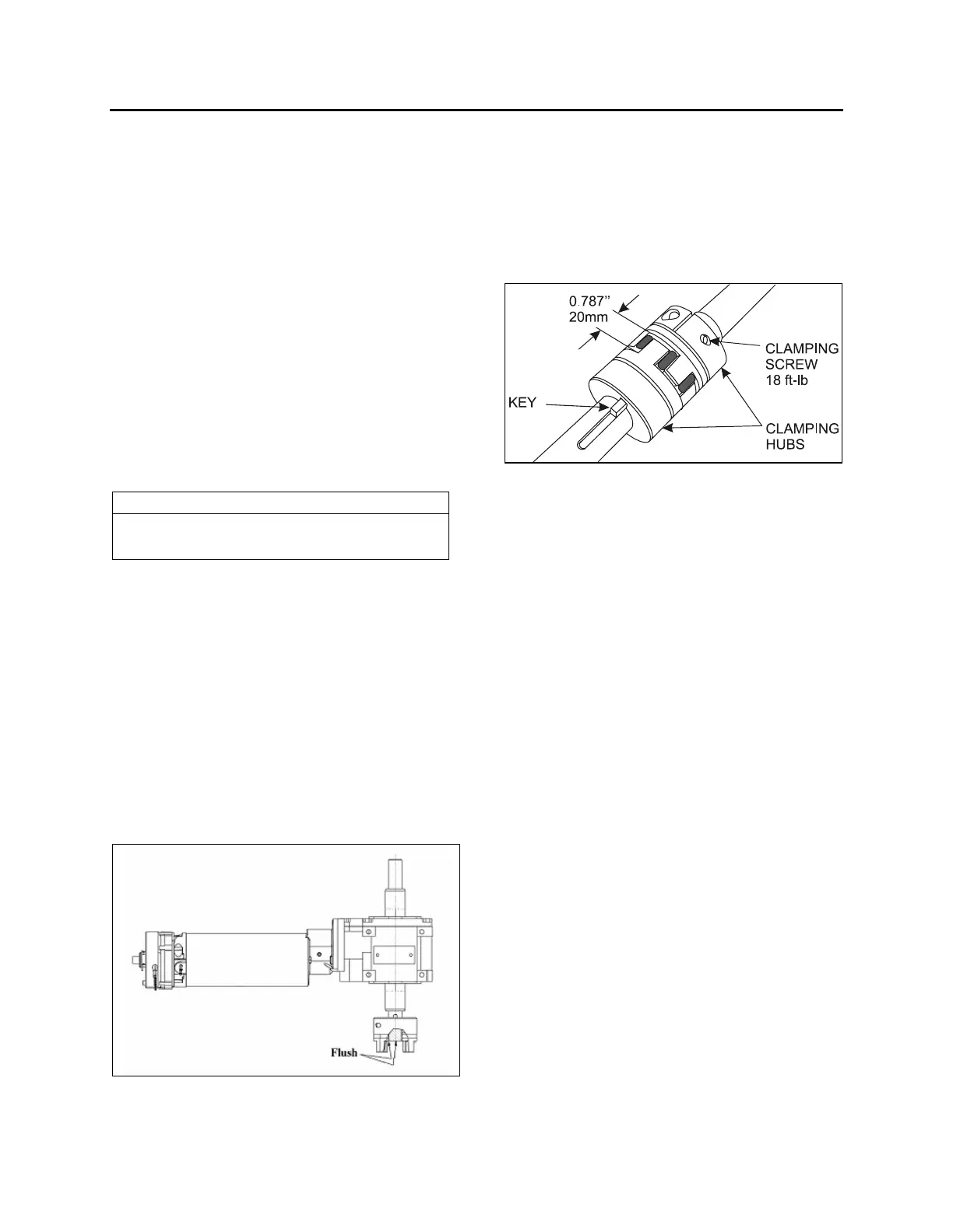
8. Reconnect the clamping hubs with the
spider. Leave a gap of 20mm (0.787inch)
between each clamping hubs as shown on
FIGURE 20. Use the motor hexagonal
socket output shaft to align the keyways.
9. Tighten clamping screws to a torque of 18
lbf-ft.
FIGURE 20: JAW COUPLING
9 FLANGE BEARING
There are two different types of flange bearing
on the slide-out mechanism (FIGURE 13). Their
purpose is to maintain the shaft in position while
permitting rotation. The gray flange bearings are
fixed to the linear bearing support plate and are
not adjustable. The blue flange bearings are
fixed to a support with oblong holes permitting to
raise or lower the flange bearing as the linear
bearing support plate level is being adjusted.
The flange bearings are pre-lubricated and no
subsequent lubrication is required due to the
very low extending and retracting speed of the
slide-out system.
10 LOCKING COLLAR
The locking collar locks the shaft and the flange
bearing together using friction. Once locked, it
permits no axial translation of the shaft and
prevents rotation of the shaft into the flange
bearing bore.
10.1 INSTALLATION
Slide the locking collar along the shaft up to the
flange bearing (FIGURE 13). Turn the locking
collar clockwise while maintaining it pressed
against the flange bearing. Knock the collar with
a punch to lock it in place, there is a cavity on
the collar made for that purpose. Tighten the set
screw.
 Loading...


