Section 06: ELECTRICAL
PA1553
27
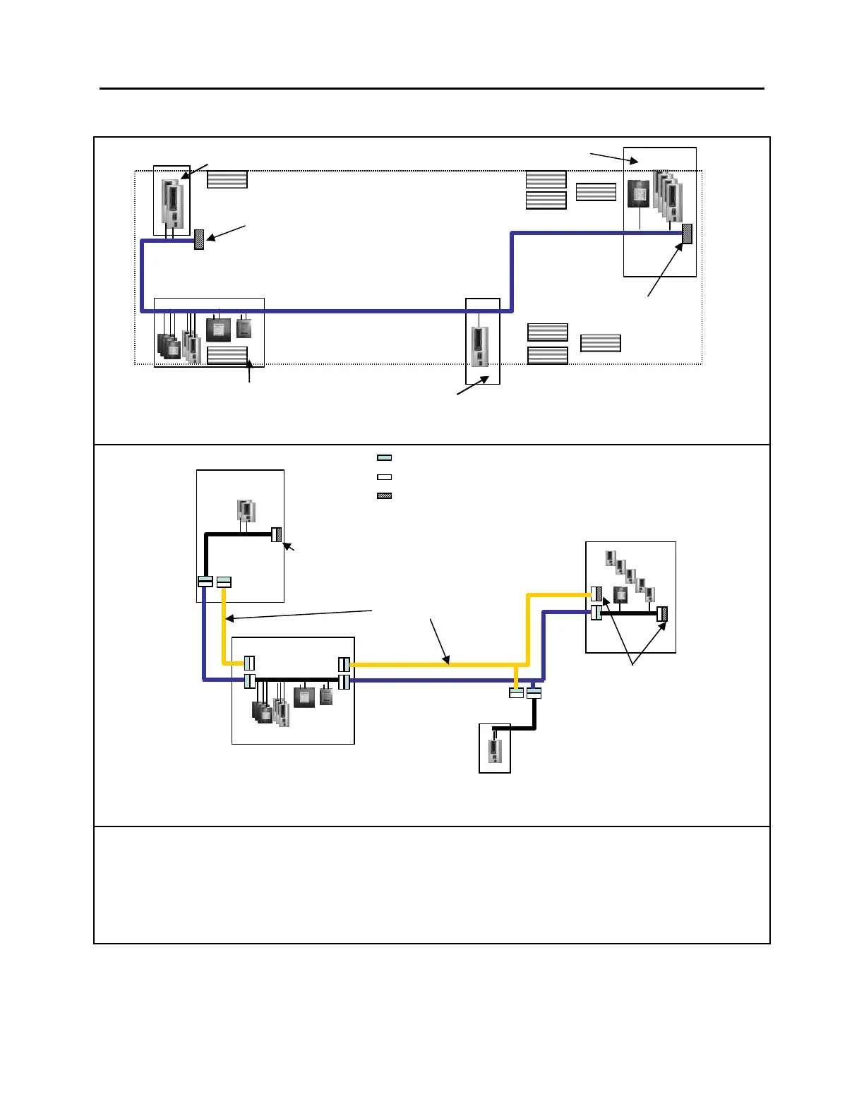
4.6 CAN NETWORK LAYOUT AND TROUBLESHOOTING
If all 14 modules (A41 to A54) are showed as Not Responding and Active Fault, the problem could be:
• A short circuit somewhere on the CAN network.
• The network is completely open circuit. That means none of the two termination resistors are
connected.
Several simple tests can be done to locate the problem.
Front electrical compartment
Evaporator compartment
Rear Junction
Box
Plug Connector 563589
Socket Connector 563590
Plug with integrated Termination Resistor 563593
C5S
C13S
C5
C1S
C3
C3S
C100
C100S
Spare CAN
Termination
Resistor
plug
Termination
Resistor plugs
Note: The termination resistor plug connected to C3S is
a spare that can be used when testing the network.
CAN network
Front electrical compartment
Evaporator compartment
/C Junction Box
Rear Junction Box
Termination
resistor
Termination
resistor
C13
Wiper control panel (right console)
Wiper control
panel
 Loading...


