Section 06: ELECTRICAL
PA1553
6
b) In first column DEVICE ID, look for device
SW102.
c) At device SW102, find the fault message,
the minimum condition to activate, other
inputs involved in logic, the multiplex module
related to switch 102, the connector and pin
number on the module and the page on
which to find the corresponding diagram.
d) Once the problem corrected, the MCD still
shows the fault as being active. You have to
leave the FAULT DIAGNOSTIC menu, wait
approximately 20 to 30 seconds and then
return to FAULT DIAGNOSTIC to request a
new diagnostic of the ELECTRICAL
SYSTEM from the CECM. The MCD should
display the fault as being inactive.
1.1.2 Testing Circuits
A careful study of the wiring diagrams should be
made to determine the source and flow of
current through each circuit. When a circuit is
thoroughly understood, a point-to-point check
can be made with the aid of the applicable
wiring diagrams. Any circuit can be tested for
continuity or short circuits with a multimeter or a
suitable voltmeter.
All electrical connections must always be kept
clean and adequately tight. Loose or corroded
connections can result in discharged batteries,
difficult starting, dim lights and improper
functioning of other electric circuits. Inspect all
wiring connections at regular intervals. Make
sure knurled nuts on all amphenol-type plugs
are securely tightened. Knurled nuts on the
plastic amphenol-type connectors will click into a
detent when properly tightened. Line
connectors, who have the side locking tabs,
must have the locks latched in place to ensure a
proper electrical connection.
1.2 WIRE SIZES AND COLORS
Each wire in the electrical system has a specific
size as designated on the wiring diagram. When
replacing a wire, the correct size must be used.
Never replace a wire with one of a smaller size.
The vehicle electrical system is provided with
different voltages. The insulation on each wire is
distinctly colored in order to determine visually
the wiring voltage and to assist in making
connectors. The wires are color coded as
follows:
Yellow Multiplex modules communication
CAN-H (twisted with green)
Green Multiplex modules communication
CAN-L (twisted with yellow)
Orange Connected to multiplex outputs
White Connected to multiplex inputs
Red 24 volt system
Yellow 12 volt system
Black grounded wire
Blue 110 V ac system (live)
Green
White
110 V ac system (ground)
110 V ac system (neutral)
Grey spare wire
NOTE
Wires are identified at each 2-4 inch (5-10 cm)
intervals by a printed number.
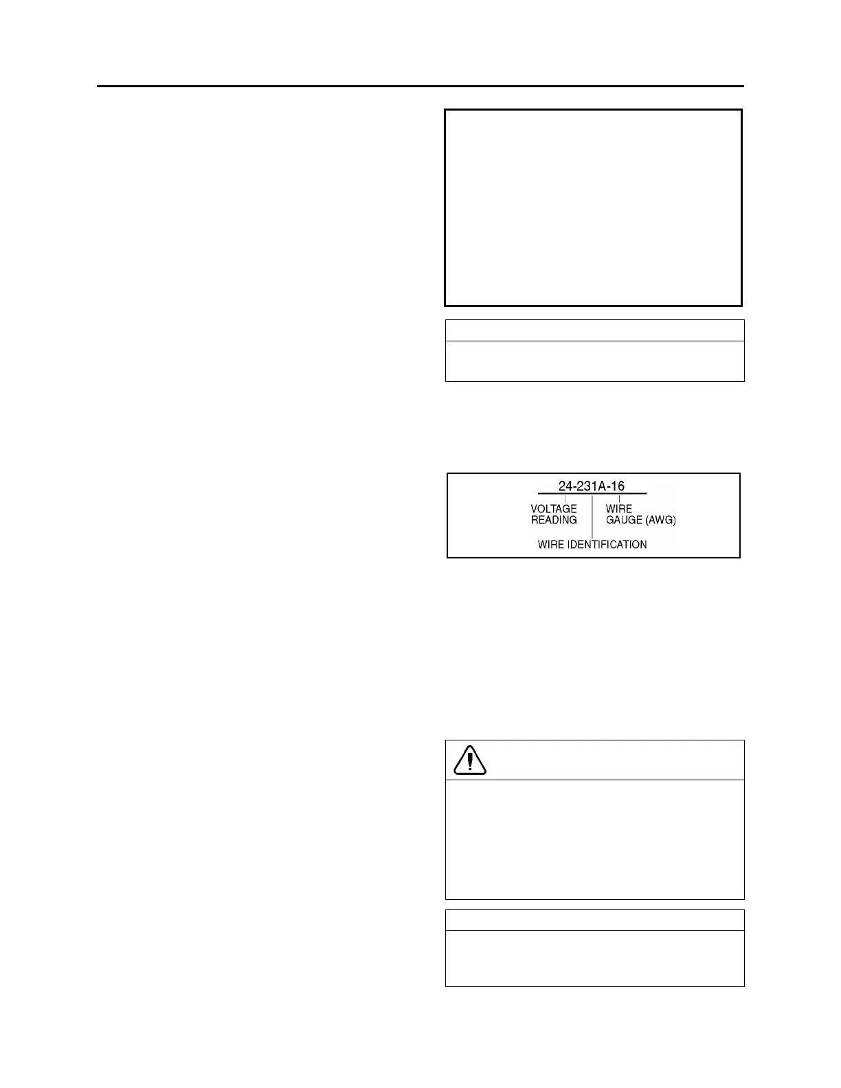
Each wire on a diagram is patterned to assist in
tracing and testing circuits. The wire number
identifies the voltage rating, the wire identification
number and the basic wire gauge as illustrated in
figure 1.
FIGURE 1: WIRE IDENTIFICATION 06048
1.3 SPARE WIRES
When the vehicle leaves the factory, and even in
the case of a fully-equipped vehicle, an
important number of unconnected spare wires
are routed between the junction boxes.
Consequently
, for any connection of an additional
accessory, refer to page D "Spare wires" in master
wiring diagram to determine the number, the gauge
and location of these wires.
CAUTION
Wire size is calibrated according to the
breaker or fuse that protects it. When using a
spare wire to replace a damaged wire, assure
that the spare wire size is equal or larger than
the wire being replaced. Using a wire too
small for the breaker or fuse amperage might
cause overheating of the wire.
NOTE
Spare wires are identified by a wire
identification number and by the letters “SP”,
to designate “spare”.
 Loading...


