Section 6: ELECTRICAL
PA1553
44
7.8 ALTERNATOR REMOVAL (DELCO)
1. Place Rear Start Panel "Starter Selector
Switch" in engine compartment to the "OFF"
position.
2. Place the ignition key switch to the “OFF”
position.
3. Remove alternator drive belt (see
“ALTERNATOR DRIVE BELT”).
NOTE
When reinstalling drive belt, it is important to
set the belt tension correctly. (Refer to the
appropriate heading later in this section).
4. Scratch off protective sealer from electrical
connections (relay, field and positive
terminals). Refer to figure 29.
FIGURE 29: ALTERNATOR (HOSES AND WIRES) 06341
NOTE
After reconnecting electrical wires, it is
important to cover terminals with protective
sealer (Prévost #680745).
5. Disconnect wire #25 from the relay terminal,
wire #107 from the field “F1” terminal and
disconnect battery cable from the positive
“+” terminal on the diode end cover. Tag
wires removed to ease identification at time
of installation. Refer to figure 29.
6. Disconnect oil supply line and vent hose
from top of alternator (Fig. 29) and tape
lines to prevent entry of foreign matter.
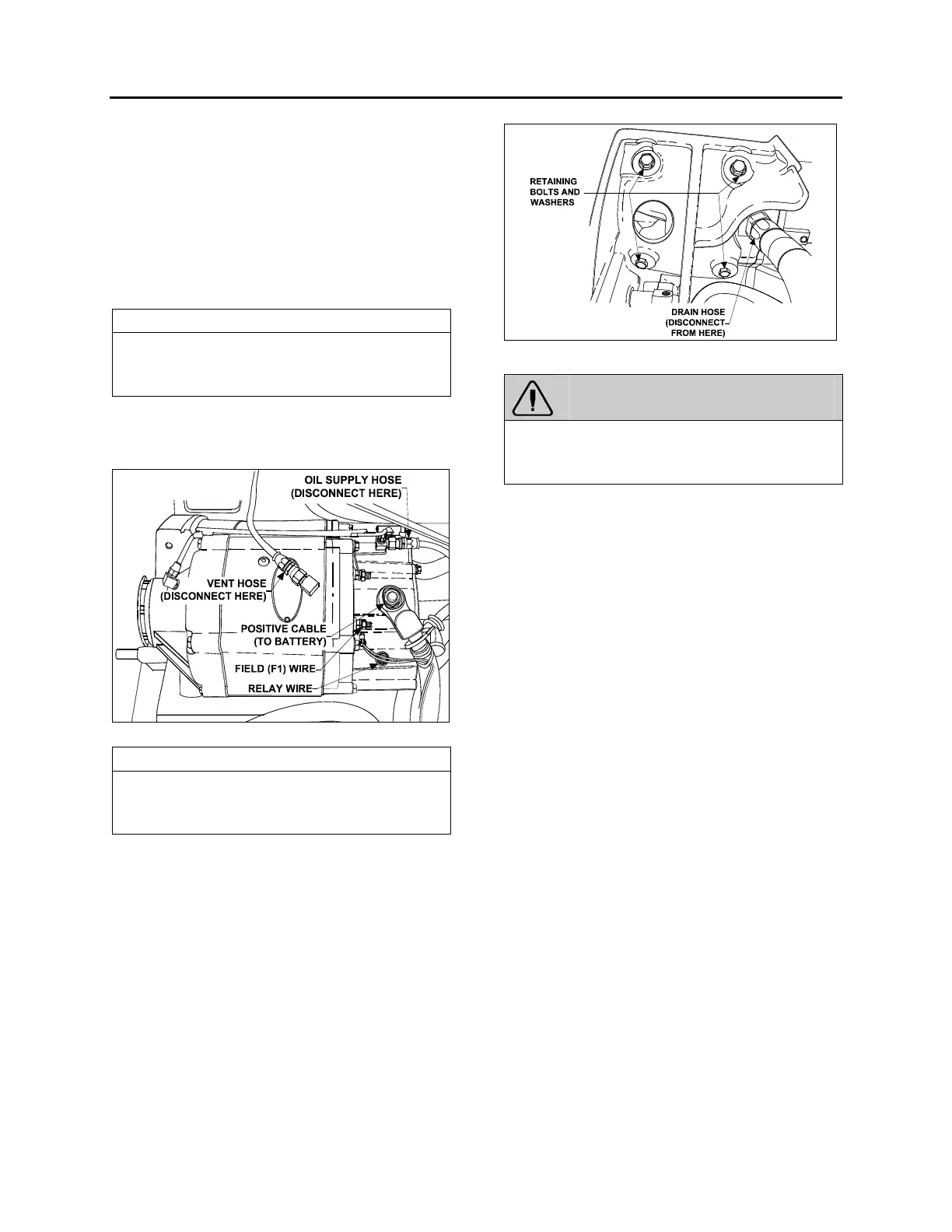
Disconnect oil drain hose from bottom of
alternator (Fig. 30) and tape line to prevent
entry of foreign matter.
7. Remove the four bolts and lock washers
fixing the alternator (refer to fig. 30).
FIGURE 30: ALTERNATOR RETAINING BOLTS AND
WASHERS
06350
WARNING
Alternator weights approximately 154 lbs (70
kg). Another person is required to take the
alternator out of the engine compartment.
7.8.1 Disassembly of Alternator
After diode, field and stator winding checks, the
alternator can be disassembled to repair a faulty
component, such as field or stator, or to proceed
with bearing or rotor replacement. Perform the
following steps to disassemble the alternator:
1. Remove nuts and washers from "DC"
terminal on diode end frame.
2. Separate the diode cover plate from the
diode end frame by removing the mounting
screws.
3. Remove the washer, nut and lock washer
attaching the diode supports to the end
frame, the three screws connecting the
diode leads to the diode supports, and the
three nuts which attach the stator studs to
the diode supports.
4. Separate the diode support assemblies from
the diode end frame, and the three nuts that
connect the studs to the diode end frame.
5. Mark the position of the drive end frame and
diode frame with respect to the stator
assembly so that the parts can be
reassembled in the same position.
6. Detach the diode end frame and field
assembly from the stator assembly by
removing the attachment screws.
7. Separate the field assembly from the diode
end frame by removing the four attachment
screws.
 Loading...


