Section 06: ELECTRICAL
PA1553
7
1.4 CLEANING CONNECTORS
When the pins and sockets of connectors
become dirty, clean them with a good quality
solvent containing HFC 134A refrigerant as its
active ingredient. HFC 134A has two qualities
that recommend it. First, it does not conduct
electricity and therefore, will not cause shorting
between connector pins and sockets. Second, it
evaporates quickly, eliminating the possibility of
condensation within the connectors.
Always shake out or gently blow out any excess
HFC 134A before assembling a connector to its
mating connector or hardware. HFC 134A
trapped in the connector can affect the
connector seal.
DANGER
HFC 134A is toxic. HFC 134A bases
compounds should always be used in a well-
ventilated area, never in a confined space.
Use outdoor whenever possible.
1.5 CIRCUIT BREAKERS
Most electric circuits are protected by circuit
breakers of the “Manual Reset” type. The main
circuit breakers, as well as those protecting the
A/C system, are located in the engine
compartment, on R.H. side of the vehicle.
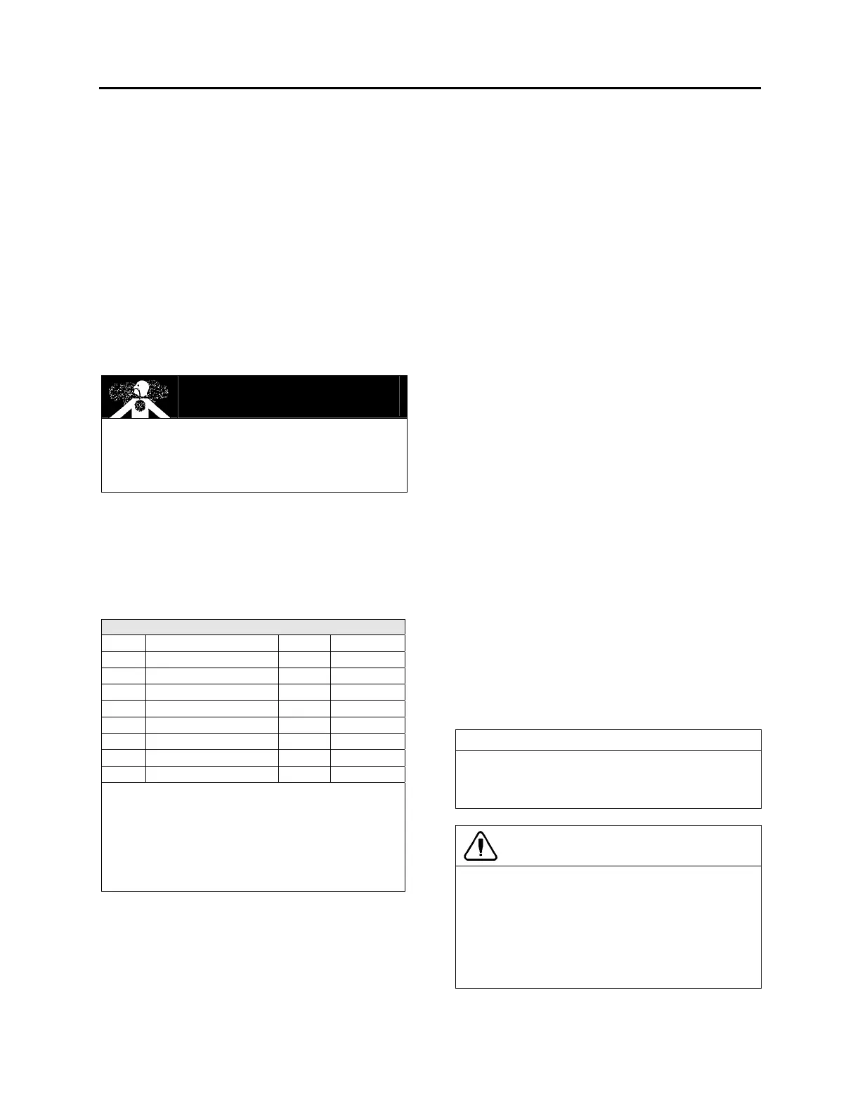
CIRCUIT BREAKERS
CB1 Distribution 12 VD 150 amps
CB2 Distribution 24 VD 50 amps
CB3 Front distribution 24 VI 70 amps
CB4 HVAC - evaporator 24 VI 90 amps
CB5 HVAC - condenser 24 VI 70 amps
CB6 Slide-Out 24 VI 35 amps
CB7 Distribution 24 VI 60 amps
CB8 HVAC - condenser 12 VI 40 amps
CB9 Distribution 12VI 70 amps
VD= volts direct. The electrical components
connected to these circuit breakers are direct-
connected to the battery.
VI= volts indirect. Electrical power is supplied
via master relay R1 which engages when
ignition key is in the ON or ACC position.
This type of circuit breaker deenergizes the
circuit without disconnecting any wire. Circuit
breakers CB1 & CB2 are different in the fact that
you may open the circuit manually, to do so
simply press down the blue tab on breaker to
trip the circuit breaker, repair defective circuit,
and afterwards toggle yellow lever upwards to
reset the circuit breaker and close the circuit.
1.6 MULTIPLEX FUSES
The multiplex outputs are protected in current by
an internal “soft-fuse”. Each output has
programmed specific maximum amperage.
When an output is shorted, the current gets
above the limit and the soft-fuse intervenes to
turn the output OFF. The output stays OFF until
the "soft-fuse" is reset.
Turn the ignition key to the OFF position and
turn to the ON position again. This resets all
"soft-fuses".
There is also hardware fuses used to protect the
incoming power to the multiplex modules. These
fuses are located inside the VECF (Vehicle
Electrical Center Front) and VECR (Vehicle
Electrical Center Rear).
1.7 RELAYS
Relays are used to automatically energize or
deenergize a circuit from a remote location. The
relay draws a very low current to energize its
coil. Once the coil is energized, it develops a
magnetic field that pulls a switch arm closed or
open, to either energize or deenergize a given
component. As the control current required for
the coil is very low, the relay allows a remote
station to control a high energy circuit without
running great lengths of costly high capacity
cable, and also eliminates the need for high
amperage switches and heavy connectors.
Many systems on this vehicle are provided with
control relays, which are all, located in or on the
junction boxes, figures 6, 9, 10 and 12.
NOTE
Each relay is identified with “12V” or “24V”
printed on its casing in order to identify the coil
operating voltage.
CAUTION
The Multiplex vehicle uses a VF4 relay
designed specially for Volvo that has different
internal characteristics than the current VF4
relay. It is important to use only the new part
marked Volvo as a replacement in Multiplex
vehicles. Regular relays have an inadequate
lifespan for Multiplex vehicles.
 Loading...


