Section 26: XLII SLIDE-OUT
PA1553
23
programmed sequence, etc. The power relays
are used to supply power coming from the I/O-B
module to the electric motor and to change
polarity to reverse motor rotation.
The I/O-B modules input signals are:
• Handheld control switch IN;
• Handheld control switch OUT;
Also, the following input signals are required for
a safe operation of the slide-out:
• Pressure transducer;
• Parking brake;
• “in limit” sensor;
• “out limit” sensor;
The I/O-B modules output signals are:
• Handheld control green indicator light;
• Power relay current reversing;
• Seal valve inflating solenoid;
• Seal valve deflating solenoid;
• Vacuum generator valve solenoid;
• Security pin valve solenoid;
• Electric motor, first power output 15 amps;
• Electric motor, second power output 15
amps;
The CECM module output signals are:
• Dashboard telltale light;
• Transmission inhibit;
DANGER
Before working on the slide-out electrical
system, turn the ignition key to the “OFF”
position.
15.1 ELECTRICAL
INTERCONNECTION WITH
PREVOST VEHICLE
The slide-out power supply comes from the 24-
volts circuit breaker (FIGURE 34) in the engine
R.H. side access compartment. The other
interconnections are located on the pneumatic
panel and the electrical panel in the front service
compartment. All the interconnections are shown
on the electrical diagrams of your vehicle.
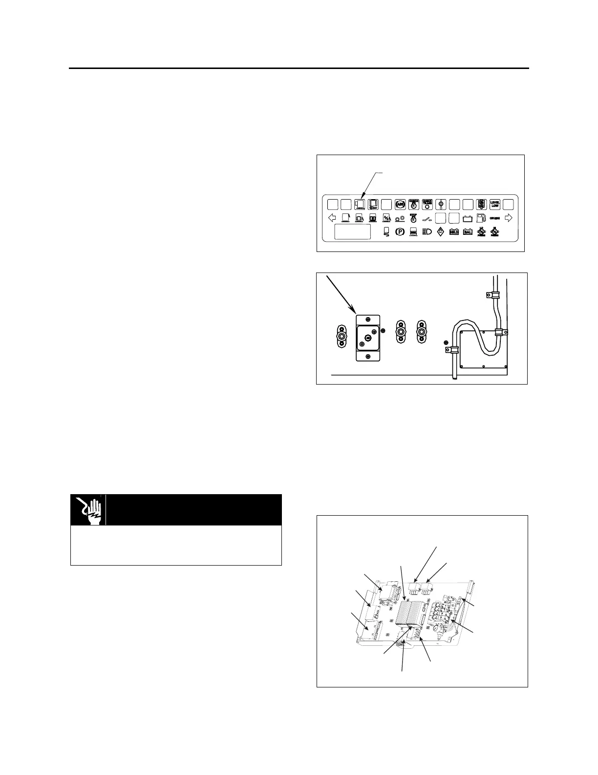
A blinking signal is added on the dashboard
telltale panel (figure 33) to indicate that an error
condition or a missing operation condition is
present on a slide-out. The slide-out telltale light
also illuminates to indicate that at least one of
the slide-outs is extended.
SLIDE
OUT
SLIDE-OUT TELLTALE LIGHT
FIGURE 33 : DASHBOARD SLIDE-OUT TELLTALE LIGHT
SLIDE-OUT
BREAKER
FIGURE 34: MAIN BREAKER IN ENGINE R.H. SIDE
ACCESS COMPARTMENT
15.2 SLIDE-OUT BREAKERS / FUSES
The main breaker (for both slide-outs) is located
in the engine R.H. side access compartment. All
other slide-out breakers and hardware fuses are
located inside the VEC, on the slide-out
electrical component panel located in the third
baggage compartment on the driver side (figure
35 and figure 36).
PNEUMATIC
COMPONENT
PANEL
PRESSURE
TRANSDUCER
SLIDE-OUT VEC
MASTER ID
CECM
FRONT SLIDE-OUT
I/O-B MODULE
FRONT SLIDE-OUT MOTOR
HIGH CURRENT RELAY (+)
REAR SLIDE-OUT MOTOR
HIGH CURRENT RELAY (+)
REAR SLIDE-OUT
I/O-B MODULE
FRONT SLIDE-OUT MOTOR
HIGH CURRENT RELAY (-)
REAR SLIDE-OUT MOTOR
HIGH CURRENT RELAY (-)
FIGURE 35 : SLIDE-OUT CONTROL PANEL
 Loading...


