Section 26: XLII SLIDE-OUT
PA1553
22
sealant on the structure surface where the
inflatable seal will be placed. Wait until the
product is dry before proceeding.
7. Install the inflatable seal on the structure,
placing it as close as possible from the
exterior side of the structure. Position the air
inlet first. Then remove locally the inflatable
seal adhesive tape protection, and press the
upper corners on the structure and hold
them in place for 90 to 120 seconds. Install
the lower corners next, then the straight
section. Press the straight inflatable seal
sections on the structure for at least 15
seconds. Use a small roller to ensure a good
adhesive contact on the structure.
8. Seal the gap between the inflatable seal and
the exterior panels and the gap between the
glasses and the fiberglass panels with
appropriate sealant. Wait until the product is
dry before proceeding. Remove excess
sealant with appropriate cleaner.
9. Replace the bushing and plug the pneumatic
tubing on the inflatable seal air inlet
(FIGURE 31).
14.3.4 Slide-out 2" inside retraction
1. For both sides of the slide-out, remove the 2
upper acetal plastic blocks shown on
FIGURE 26 (refer to section 13).
2. Manually deflate the seal completely by
turning the relieving shut-off valve clockwise
(FIGURE 29). Make sure the pressure
indicator reading is "0 psi".
3. Turn the ignition to the off position. Using
the manual override procedure (section 18),
extend the slide-out a few inches so the
exterior extrusion screws located on the top
of the slide-out are accessible from outside
(figure 7).
4. Using a knife cut the sealant between the
extrusion and the roof (figure 7). Unscrew
and remove the central exterior extrusion
screws and the two end extrusion screws.
CAUTION
Do not use the slide-out handheld control to
move the slide-out 2" inside the vehicle,
because the limits are not recognized over the
closed position. The slide-out will not stop and
damage may occur.
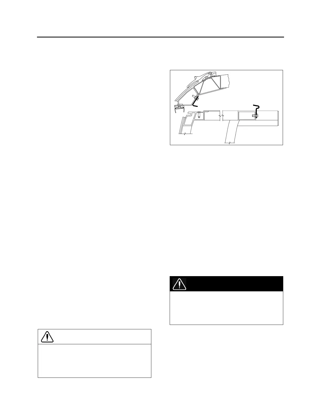
5. Using the manual override procedure, move
the slide-out 2" inside the vehicle, so the
seal is accessible from outside (FIGURE
32).
FIGURE 32: SLIDE-OUT 2" INSIDE – UPPER PART
6. Once completed, use the manual override
procedure to extend the slide-out to reinstall
the exterior extrusion. Apply appropriate
sealant on the exterior extrusion screws and
between the extrusion, the roof and the
edges to prevent water infiltration (FIGURE
32).
7. Reinstall the acetal plastics blocks.
8. Using the manual override procedure,
retract the slide-out to its closed position.
9. Finally, the seal can be re-inflated by turning
the shut-off valve handle counterclockwise.
Check the pressure gage on the inflatable
seal regulator to see if the pressure is
increasing to 10 psi.
15 SLIDE-OUT ELECTRICAL
SYSTEM
DANGER
Never modify the slide-out electrical wiring
without the Prevost Car approval. Any
modifications may cause an unexpected slide-
out action and could result in personal
injuries.
The multiplexed slide-out electrical system is
mainly composed of the Master ID module, the
CECM module, the VEC module and two I/O-B
modules.
Each slide-out has its own I/O-B module and two
power relays. The I/O-B modules analyze the
input signal conditions and activate outputs like
the pneumatic valves, the retracting or extending
 Loading...


