Section 6: ELECTRICAL
PA1553
47
components are mounted on a printed circuit
panel board to form a completely static unit
containing no moving parts. Regulators of this
type have only four terminals which are
identified "GND." (ground), "FLD" (field) "BAT"
(battery) and “IGN” (ignition).
FIGURE 32: VOLTAGE REGULATOR 06408
The regulator components work together to limit
the alternator voltage to the preset value by
controlling the alternator field current. This is the
only function that the regulator performs in the
charging system.
The voltage at which the alternator operates is
determined by the regulator adjustment. Once
adjusted, the alternator voltage remains
constant. The regulator is unaffected by length
of service, changes in temperature, or changes
in alternator output and speed.
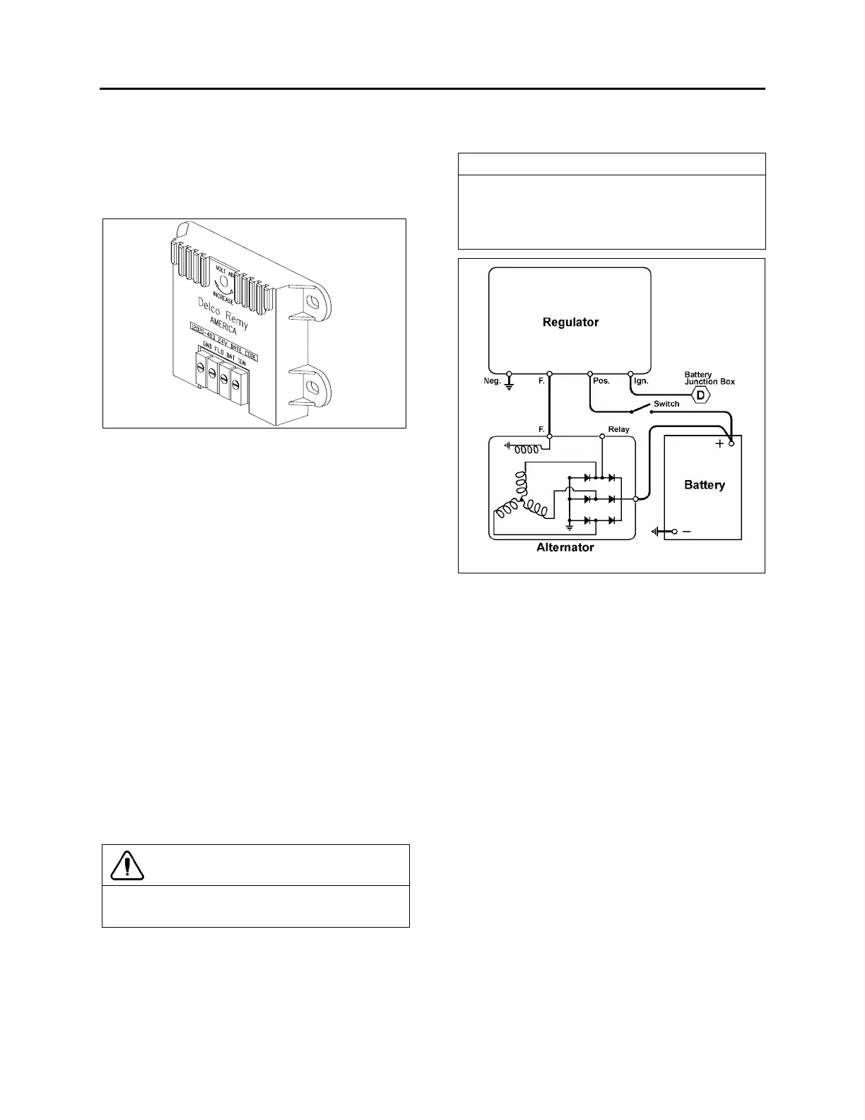
A typical wiring diagram of a negative ground
system is illustrated in figure 33. This diagram
shows only the basic charging system
components. It does not show any components
such as the control relays. Refer to “Charging
system” wiring diagram, in “Wiring diagrams” for
the electric circuits and connections.
Voltage regulator maintenance
The voltage regulator is a service-free electronic
unit. When it fails, it should be replaced. The
following procedure must be used:
CAUTION
Set the ignition key switch to the “OFF”
position.
o Open the engine compartment R.H. side
door in order to get access to the voltage
regulator;
o Unscrew the electrical cable connectors;
o Unscrew the voltage regulator unit;
o Install a new voltage regulator by reversing
the procedure.
NOTE
For information about BOSCH alternator and
voltage regulator, refer to technical publication
"Repair and Testing Instructions for T1
Alternator 0120 689 552".
FIGURE 33: TYPICAL WIRING DIAGRAM OF A NEGATIVE
GROUND SYSTEM
06415
8.1 TROUBLESHOOTING PROCEDURES
Trouble in the electrical system will usually be
indicated by one of two conditions: an
undercharged or an overcharged battery. Either
condition can result from an improper voltage
regulator setting:
Checking Battery Voltage
The absence of gas production during the
continuous appearance of the green dot in the
battery’s built-in hydrometer indicates that the
voltage setting is satisfactory. Check the
following conditions:
Checking Voltage Regulator Setting
1. To check the voltage setting, connect a
voltmeter across the “POS” and “NEG”
terminals on the regulator, and an ammeter
to the “C” terminal on the alternator. Refer to
figure 34.
2. Operate the engine at approximately 1000
rpm (about 2300 alternator rpm), with
accessories on, to obtain an alternator
output of 20-200 amperes.
 Loading...


