Section 06: ELECTRICAL
PA1553
24
4.3 CAN NETWORK
The CAN link wiring is separated in sections and
uses connectors that are not shared with other
circuits. This allows sections of the network to be
isolated to help locate short-circuit on the CAN.
In case of a short-circuit on the CAN link, this
affects all the modules and they all show « No
Response » in the error messages of the
« ELECTRICAL SYSTEM » menu. To locate a
short-circuit, proceed by disconnecting one
module zone at a time while verifying if this
makes inactive the errors in the modules still
connected. Connector C1 (front electrical &
service compartment) disconnects all the
modules at the rear of the vehicle from the
network. Connector C5 (front electrical & service
compartment) disconnects all the modules from
the wiper control panel. Connector C100
disconnects the module from the evaporator
compartment. Connector C3 (rear junction box)
disconnects the modules from the battery
compartment.
Example: Disconnect C5 and C1 and then verify the
status of the errors. If the front modules (A41 to A46)
now give inactive errors, which means short-circuit is
elsewhere than in the front electrical & service
compartment.
4.3.1 Can Connection On The Telltale Panel
And The Hvac Control Unit
The telltale panel module and HVAC module are
linked to the CECM by a CAN connection. In
case of a CAN connection default, the telltale
panel LCD display shows "CAN", and on the
HVAC control unit, the temperature display
indicates "---". To confirm a CAN connection
default, check that the fan speed on the driver's
section HVAC control unit cannot be adjusted.
Moreover, specific error messages from these 2
modules can be read in the ELECTRICAL
SYSTEM menu.
NOTE
While downloading a new vehicle program in the
CECM from a computer, the CAN network is
temporarily interrupted and therefore a CAN
reference appears in the telltale panel LCD
display.
4.3.2 Spare Can
A spare CAN network is installed between the
front and the rear of the vehicle. It has
connectors installed at each end to facilitate
swapping from the regular CAN network to the
spare CAN network. Refer to the vehicle wiring
diagram and paragraph 4.6 for more information.
4.4 TEST MODE FOR SWITCHES AND
SENSORS
The switch/sensor test mode provides useful
information to diagnose problems complimentary
to the electrical system diagnosis.
To enter this mode, activate the dashboard
"Telltale Light Test" switch 3 times within 4
seconds. To exit the switch/sensor test mode,
reactivate the test switch 1 time or turn OFF the
ignition.
4.4.1 Information Available And Impact On
The Functions In Switch/Sensor Test
Mode
Telltale panel audible alarm emits a beep each
time an OFF/ON transition is detected on a
multiplex input. This allows quick verifying if the
switches and sensors are detected or seen by
the multiplex modules. When the vehicle is
parked, the back-up alarm also emits a sound
that allows verification of the sensors at the rear
of the vehicle.
Certain inputs are doubled (ex. turn signal switch
on multi-function lever) and also other inputs
activate at the same time. For these inputs, 2
beeps are emitted. If only one beep is heard, one
of the inputs is defective.
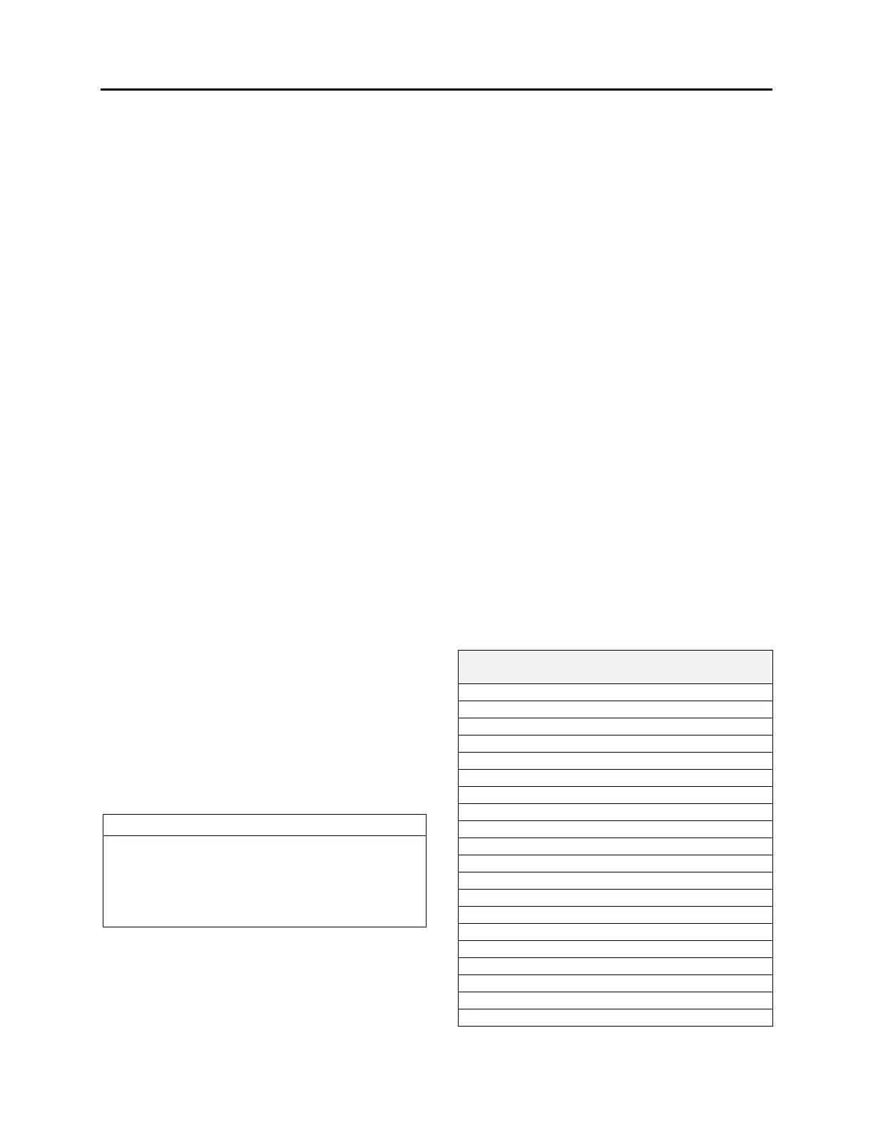
SWITCHES AND SENSORS SUPPORTED
BY THE SWITCH/SENSOR TEST MODE
HVAC control unit driver’s section ON/OFF
A/C door ajar open sensor
HVAC control unit driver recirculate switch
HVAC control unit cabin area ON/OFF
Engine ether start switch
Radiator fan clutch switch
Engine front start enable switch
Engine rear start enable switch
Engine ignition front switch
Engine ignition rear switch
Entrance door electric window down switch
Entrance door electric window up switch
Electric horn button
Interior lighting switch, 2 positions
Driver’s area lighting switch
Reading lights switch
Multi-function lever LH turn signal
Multi-function lever RH turn signal
Fog lights switch
Hazard warning flashers switch
 Loading...


