Repair and Testing Instructions for T1 Page 28
Alternator 0120 689 552 Edition 001
All rights rest with Robert Bosch Corp, including patent rights. All rights of use of reproduction and publication rest with R. B. Corp.
UA/ASV 04.12.98 T1ALTFinal.DOC
Note: Do not allow the spacer ring to twist while pressing onto the rotor.
8. Place the inner bearing race of the collector end shield bearing onto the rotor shaft.
9. Press the bearing onto the rotor shaft with tool KDLJ 6018. (Figure 26)
10.2 Drive End Shield Assembly
1. Insert sealed ball bearing into the drive end shield.
2. Align the holes of the bearing cover plate with the holes in the drive end shield.
3. Start the four screws which hold the bearing cover plate and tighten to 4.1 … 5.5 Nm (36.3 … 48.7 in. lbs.)
(Figure 27)
4. Insert bearing/fan spacer ring into the drive end shield from the fan side of the shield.
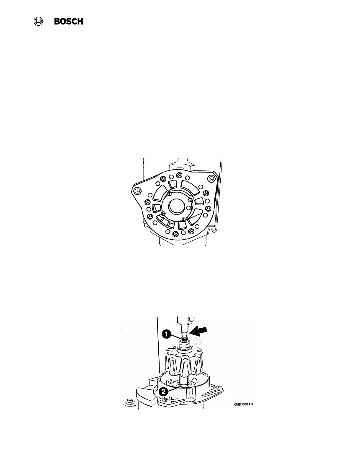
5. Place drive end shield on to an arbor press with the bearing/fan spacer ring pointed down. (Figure 28)
6. Slide support ring onto the drive end of the rotor. Make sure the under cut side of the ring faces the
retaining ring on the rotor.
Figure 28 Installing Rotor into Drive End Shield
(1) Tool KDLJ 6018 (2) Support Ring
Figure 27 Drive End Bearing Retaining Screws
 Loading...


