Section 26: XLII SLIDE-OUT
PA1553
6
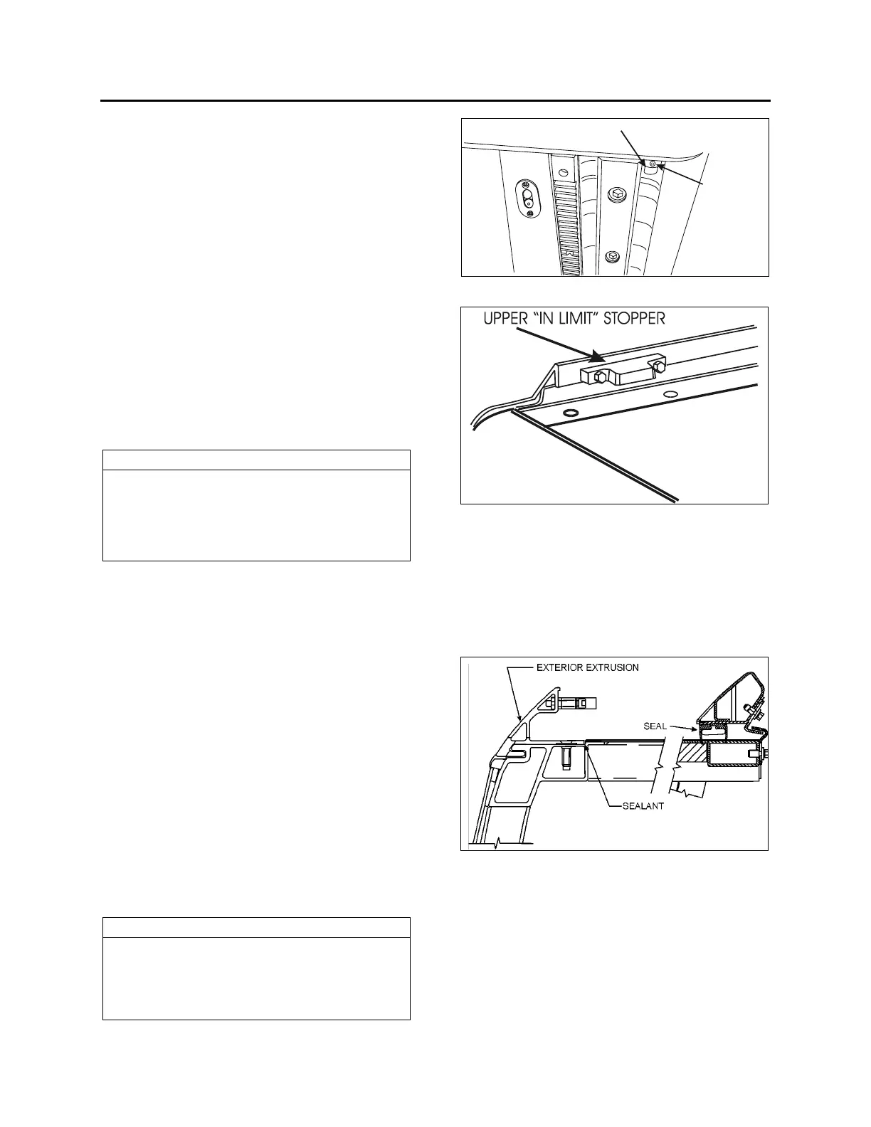
1.2 "IN LIMIT" STOPPER
Each slide-out has four "in limit" stoppers. Two
"in limit" stoppers are mounted on the exterior
extrusion at the top of the slide-out (FIGURE 6)
and two other "in limit" stoppers are mounted
under the slide-out, next to the rail (Figure 5).
These stoppers are use to position the outer
face of the slide-out flush with the vehicle body
when retracted.
1.2.1 Maintenance
Check that the "in limit" stoppers are clean and
that there is no foreign matter accumulated
between the stopper and their bearing surface.
Check that the screws and set screws (where
applicable) locking the stoppers in proper
position are tight.
1.2.2 Adjustment
NOTE
To properly adjust the “in limit” stoppers, the
slide-out system must be turned off to prevent
the “in limit” sensors from stopping the slide-
out movement before having the “in limit”
stoppers contacting their bearing surface.
1. Extend the slide-out partially.
2. Set the ignition switch to the OFF position.
3. To adjust the lower "in limit" stoppers,
loosen the set screw and then rotate the
stopper CW or CCW to move it back or
forward depending on the required
adjustment. To adjust the upper plastic "in
limit" stoppers, add or remove shims as
required between the stopper and the
extrusion.
4. Using the manual override procedure
(section 18), move the slide-out up to its full
"in" position.
5. Using a straight edge, check if the outer face
of the slide-out is flush with the vehicle body
with the stoppers contacting their bearing
surface. Readjust the stoppers if necessary.
6. Readjust the “in limit” sensor.
NOTE
To make sure that the lower “in limit” stoppers are
contacting their bearing surface (the acetal plastic
blocks) when the slide-out is closed, put white paint
on the “in limit” stopper before and check if the
acetal plastic blocks are marked with paint.
LOWER “IN LIMIT” STOPPER
SET
SCREW
FIGURE 5: LOWER "IN LIMIT" STOPPER
FIGURE 6: UPPER "IN LIMIT" STOPPER
1.3 EXTERIOR EXTRUSION
The exterior extrusion function is to provide a
leaning surface for the inflatable seal. When
inflating, the seal leans against the extrusion and
presses the roof structure upward until it rests on
the inner side of the extrusion.
FIGURE 7 : EXTERIOR EXTRUSION
Maintenance
Inspect the exterior extrusion for any
deformation or deterioration. Check that the
screws are tight. Inspect the sealant condition on
screw head and between the extrusion and the
vehicle structure, and also at both ends of the
extrusion. If needed, clean old sealant and
replace with Sika 221 sealant or equivalent
product.
 Loading...


