Section 26: XLII SLIDE-OUT
PA1553
5
1 SLIDE-OUT
1.1 INNER STOPPER
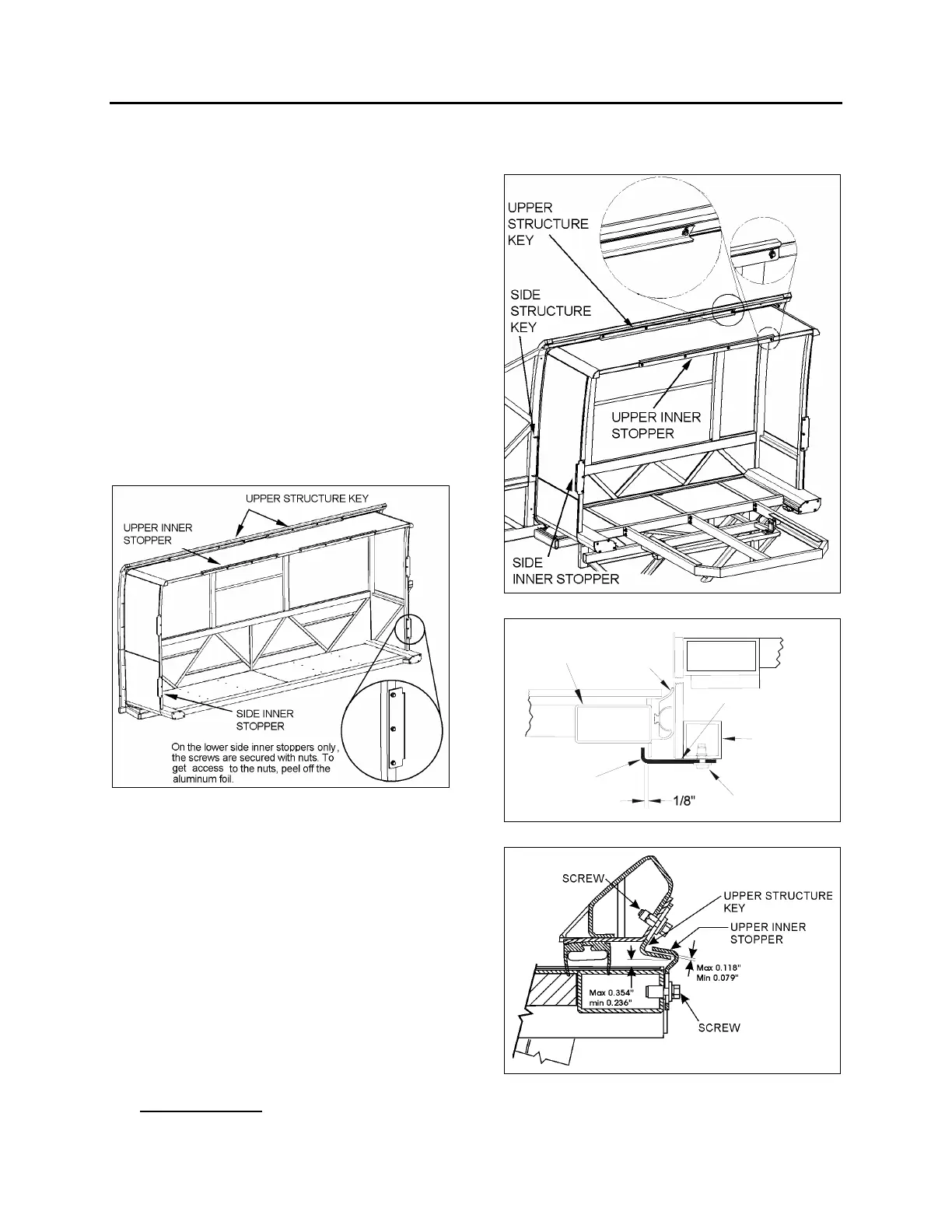
The front slide-out is equipped with six inner
stoppers laid out in the following way: two
stoppers on the top horizontal member of the
slide-out, and two stoppers on each vertical
upright, while the rear slide-out is equipped with
only three stoppers (figure 1 and figure 2). The
upper inner stoppers are used to provide a
support to position perpendicularly the slide-out
with the vehicle structure.
The side inner stoppers are used to block the
extension of the slide-out. They act as ultimate
physical limits but take note that when the “out
limit” sensors are properly adjusted, the slide-out
extension stops before the side inner stoppers
reach the side structure keys (figure 1 & 2).
FIGURE 1 : FRONT SLIDE-OUT
1.1.1 Maintenance
Check that the inner stopper screws are tight
and that no damage or deformation has taken
place for both the side and the upper stoppers.
1.1.2 Adjustment
1. Adjust the side inner stoppers at 1/8" from
the vehicle side structure keys, and tighten
the screws. Make sure there is a minimum
gap of 2mm (0.079”) between the side inner
stopper and the side window pane (figure 3).
Use shim as required.
2. Adjust the upper structure key and the upper
inner stoppers according to FIGURE 4 with
the seal deflated
. When inflating, the seal
presses the roof structure upward and at
that moment, the upper inner stopper comes
into contact with the upper structure key
FIGURE 2 : REAR SLIDE-OUT
SCREW
SLIDE-OUT
STRUCTURE
SEAL
VEHICLE
STRUCTURE
SIDE INNER
STOPPER
2mm (0.079in)
MINIMUM GAP
FIGURE 3 : SIDE INNER STOPPER ADJUSTMENT
FIGURE 4: UPPER INNER STOPPERS ADJUSTMENT
 Loading...


