Section 22: HEATING AND AIR CONDITIONING
PA1553
43
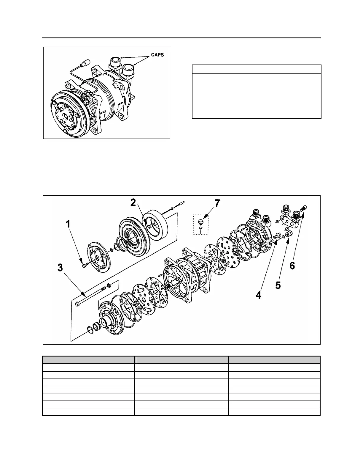
FIGURE 48: DISCHARGE AND SUCTION CAPS
* Fill the compressor with refrigerant through
connector’s suction port raising the pressure
to at least 0.5 Mpa (70 psi).
* Check the compressor for leaks using a leak
detector.
NOTE
Never leave the compressor upside down for
longer than 30 seconds. This is because the
oil inside the compressor will enter the
cylinders, causing liquid compression which
will damage the compressor’s suction and
delivery valves.
10.12 TIGHTENING TORQUES
FIGURE 49: TIGHTENING TORQUES
PART THREAD SIZE TIGHTENING TORQUE
1. Bolt Armature M6 x 1.0 12 - 14 Nm (8.7 - 10.1 Lbf-Ft)
2. Field Coil Screw M5 x 0.8 4 - 6 Nm (2.9 - 4.3 Lbf-Ft)
3. Body Bolt M8 x 1.25 20 – 24 Nm (14.5 – 17.3 Lbf-Ft)
4. Oil Drain Plug M8 x 1.25 13 – 15 Nm (9.4 – 10.8 Lbf-Ft)
5. Pressure Relief Valve 3/8 – 24UNF 13 – 15 Nm (9.4 – 10.8 Lbf-Ft)
6. Connector Bolt M8 x 1.25 20 – 24 Nm (14.5 – 17.3 Lbf-Ft)
7. Oil Filler Plug M8 x 1.25 13 – 15 Nm (9.4 – 10.8 Lbf-Ft)
 Loading...


