Section 26: XLII SLIDE-OUT
PA1553
16
slide-out level. The distance between the top
of the horizontal member under the slide-out
and the slide-out under panel must be
21mm (13/16” approximately).
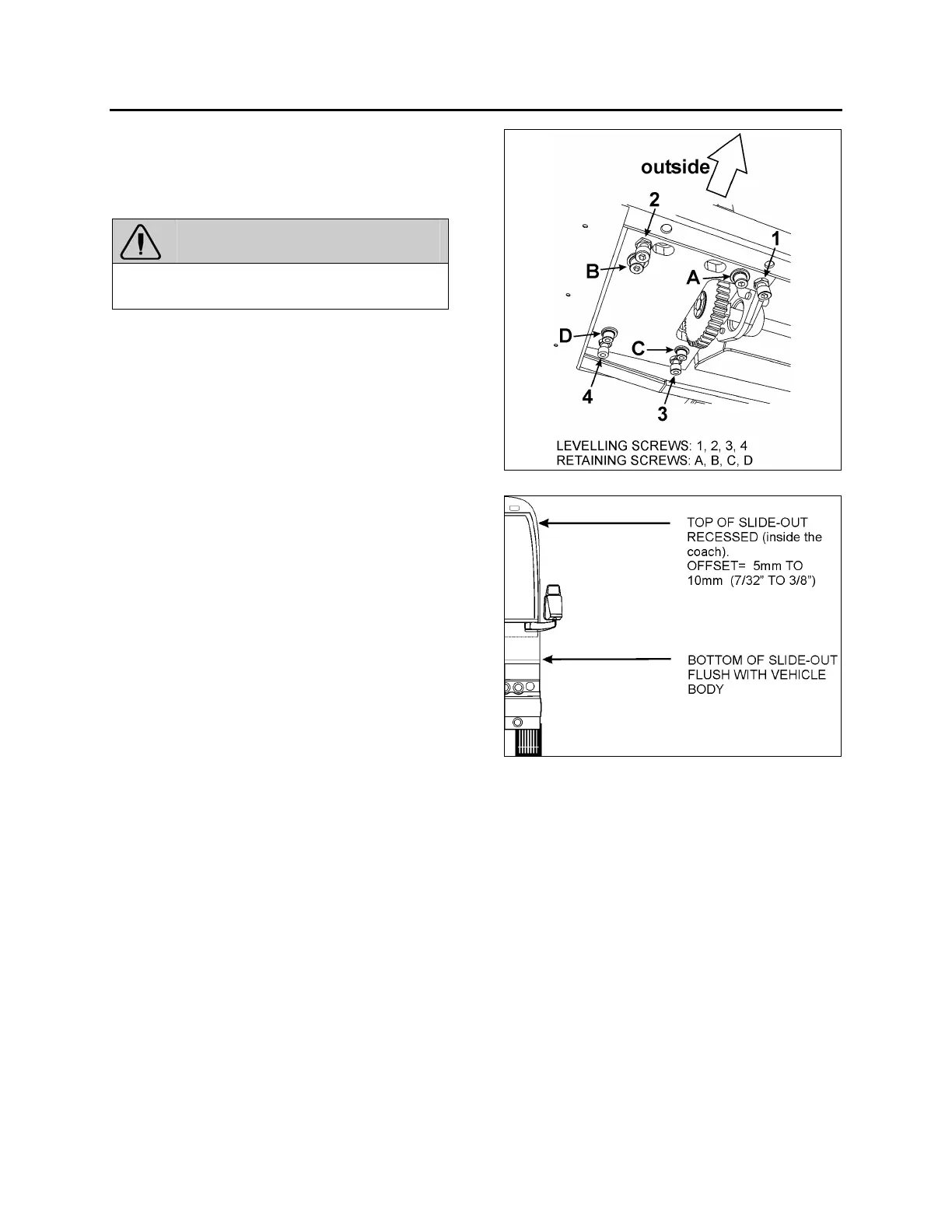
WARNING
Never unscrew completely retaining screw A,
B, C, D or the slide-out may tip inside.
To raise the linear bearing support plate, turn
levelling screw 1 & 2 clockwise. Slightly and
gradually, loosen the retaining screws A & B as
the support plate elevates, but keep the retaining
screws tighten.
To lower the linear bearing support plate, turn
screw 1 & 2 counterclockwise. As the support
plate goes down, maintain the retaining screw A
& B tighten.
4. Loosen retaining screws C & D. Unscrew
leveling screw 4. Now, the support plate
should be resting on levelling screw 1, 2 & 3.
5. Using levelling screw 3, adjust the tilt in
order to have the top of the slide-out
recessed between 5mm and 10mm (7/32"
and 3/8") (see FIGURE 23).
6. When proper tilt is attained, tighten leveling
screw 4 so that it comes into contact with the
support plate.
7. Loosen slightly levelling screw 3 and then
tighten it so it is perfectly in contact with the
support plate. Make sure screws 1, 2, 3 & 4
are in contact with the support plate.
8. Loosen retaining screw A & B.
9. Using a crisscross pattern, tighten
progressively (3 rounds) the retaining screw
A, B, C & D to a torque of 50 ft-lb.
10. Assure that the levelling screw 1, 2, 3 & 4
are firmly leaning on the support plate and
then firmly tighten the jam nuts.
11. Verify that the tilt is still properly adjusted
(between 7/32" and 3/8").
FIGURE 22 : SLIDE-OUT LEVELING
FIGURE 23: TILT ADJUSTMENT
12 RAIL
Rail and linear bearing system provide precise
frictionless linear movement together with high
load carrying capacity and high stiffness. These
standardized equipments are fully
interchangeable.
To prevent corrosion, an electrolytic black film
treatment is performed to the rail. Do not strike
the rail with metal tools, this could damage the
treatment.
After the rail is mounted to the slide-out base, a
cap is used to cover the bolt hole to prevent
foreign matters from clogging up the hole or from
entering into the ball slide. The cap for the bolt
hole is made of synthetic resin which is superb
in its resistance to oil and wear.
 Loading...


