Section 26: XLII SLIDE-OUT
PA1553
17
12.1 MAINTENANCE
Check that all the caps for the bolt hole are
present. Missing caps must be replaced. To
insert a cap into the rail bolt hole, use a flat tool.
Pound the cap gradually until its height becomes
flush with the rail top face.
Clean accumulated dirt from the rails with a soft
cloth.
12.2 REPLACEMENT
1. Remove the slide-out from the vehicle
(removal must be performed according to
the Slide-Out Removal Procedure. Ask to
your Prevost service representative).
2. Remove the bolt hole cap covers. To do so,
pierce a hole in the center and hook them
out. They will not be reusable.
3. Remove the rail mounting bolts.
4. Wipe off the rust preventive oil applied to the
new rail. Remove burrs and small bumps on
the slide-out mounting face with an oilstone.
5. Carefully place the rail on the bed on its
mounting face.
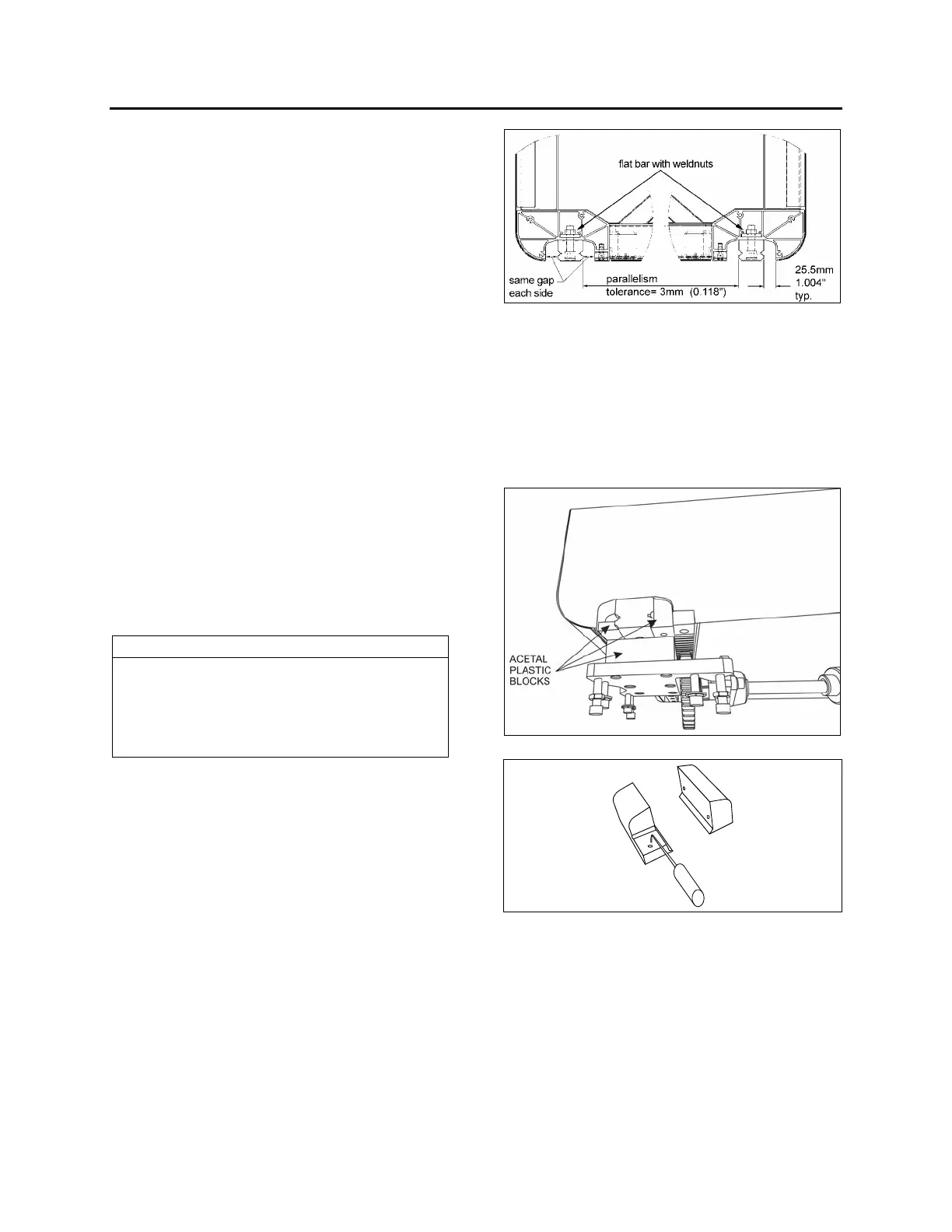
NOTE
The rail is bolted to a flat bar on which
weldnuts are mounted. The flat bar is inserted
in the slide-out lower body extrusion and can
be removed through the end cap (FIGURE
24).
6. Adjust the flat bar position to align the
weldnuts with the rail mounting holes.
7. Temporarily tighten the bolts.
8. Adjust the rail position with as per FIGURE
24. For each rail, make sure the gap is the
same both side of the rail.
9. For final tightening of the bolts, tighten on
either end of the rail and then start to the
other end. Tighten to a torque of 95 ft-lbf.
Use blue Loctite ™ on threads.
10. Cap the bolt holes.
FIGURE 24 : RAIL POSITIONING
13 ACETAL PLASTIC BLOCKS
Three different acetal plastic blocks are installed
next to each linear bearing to prevent dirt and
foreign matter from entering inside the vehicle.
They also serve as bearing surface for:
1. The inflatable seal each side of the rail.
2. The “in limit” stoppers.
FIGURE 25: ACETAL PLASTIC BLOCKS
FIGURE 26: REMOVE THE UPPER ACETAL PLASTIC
BLOCKS WITH A PICKING TOOL
13.1 REMOVAL / INSTALLATION
1. Gain access to the linear bearing support
plate.
2. From under the support plate, remove the
acetal plastic block mounting screws (see
the oblong holes on figure 22).
 Loading...


