Section 22: HEATING AND AIR CONDITIONING
PA1553
31
vaporization of the refrigerant. The gas
continues along in the evaporator and remains
at the same pressure. However, its temperature
increases due to the continued absorption of
heat from the surrounding atmosphere. The
degree to which the gas refrigerant is
superheated is related to the amount of
refrigerant being fed to the evaporator and the
load to which the evaporator is exposed.
FIGURE 34: EXPANSION VALVE 22045
Superheat Adjustment
The starting method of adjusting the superheat
is to unscrew completely the main evaporator
expansion valve adjusting screw, then screw in
13 turns clockwise for 134A (Fig. 35).
Afterwards, the following procedure should be
followed:
1. Operate vehicle for at least one-half hour at
fast idle with temperature control set at 82
o
F
(27,7
o
C), Then set temperature to minimum
to keep the compressor on 6 cylinders.
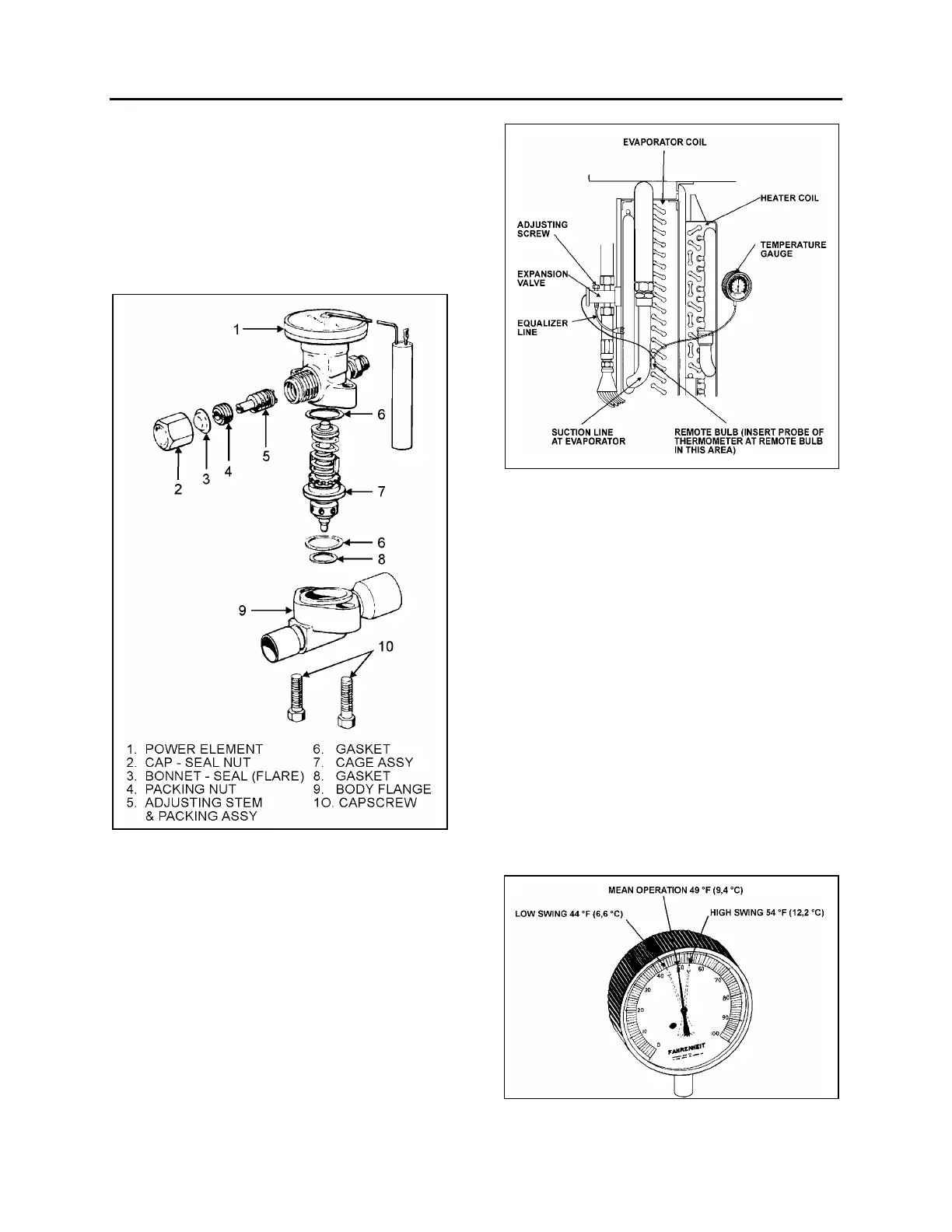
FIGURE 35: SUPERHEAT ADJUSTMENT INSTALLATION22046
2. Install pressure gauge at the evaporator
suction header. You may install the
pressure gauge at compressor suction, but
then add 3 psi to reading.
3. Install a remote reading thermometer to the
evaporator outlet line near the existing
remote bulb (Fig. 35).
4. Apply thermostatic tape around the bulb
and evaporator outlet line to get a true
reading of the line temperature.
5. Block condenser if necessary to keep
pressure over 150 psi.
6. Check approximately 5 readings of
pressure at 2-minute intervals and convert
to temperature using the temperatures &
pressures table (page 31). Likewise check
the temperature reading at the remote bulb
at the same 2-minute intervals and record
the low and high swing readings of the
needle (refer to Fig. 36).
FIGURE 36: HIGH & LOW SWING TEMPERATURE AT
REMOTE BULB
22047
 Loading...


