Section 22: HEATING AND AIR CONDITIONING
PA1553
47
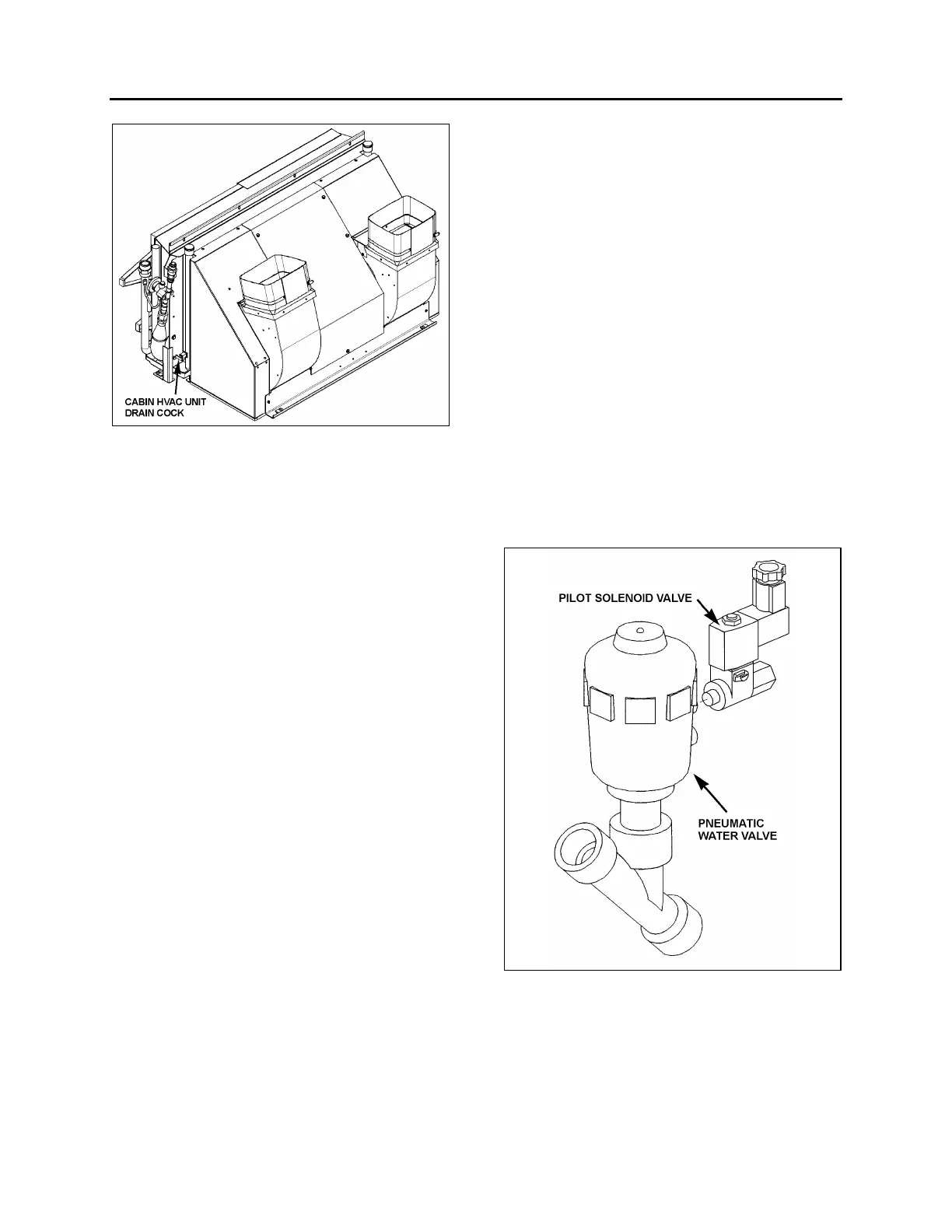
FIGURE 55: CABIN HVAC UNIT DRAIN COCK 22128
11.1.2 Filling Heating System
1. Ensure that the drain hose is reconnected
and the manual vent and drain cock are
closed.
2. Open the surge tank filler cap and slowly fill
the system to level of filler neck.
3. After initial filling, the water valves should
be open and the water recirculating pump
should be energized to assist in circulating
coolant through the heating system. To
perform this operation, start the engine,
switch on the HVAC control module, both
driver’s and cabin (passenger) areas, and
set temperature to their maximum positions
in order to request the heating mode in
each of these areas.
4. When coolant level drops below the surge
tank filler neck, slowly fill the system to level
of filler neck.
5. Once the level has been stabilized, replace
cap.
11.1.3 Bleeding Heating System
Whenever the heating system has been drained
and refilled, or the system has run low on
coolant and coolant has been added, it is
necessary to bleed air from heating system.
Locate the manual vent illustrated in Figure 52
and open momentarily until no air escapes from
the line.
11.1.4 Soldering
Before soldering any part of the system, make
sure the area is well ventilated. Use (stay clean)
flux sparingly and apply solder (95-5 round wire
1/8 inch [3,1 mm]). After completing repairs, test
for leaks.
When using heat at or near a valve, wrap with a
water saturated rag to prevent overheating of
vital parts.
11.1.5 Driver’s Hot Water Pneumatic valve
Assembly
o Description
The flow of hot water to the driver’s heater core
is controlled by a pneumatic NO water valve
assembly. The valve, located at the ceiling of the
spare wheel compartment, is designed so that
the pilot solenoid valve, which is part of the
assembly, opens and closes a port which directs
air pressure to the actuator casing, thereby
opening or closing the valve.
FIGURE 56: DRIVER'S HOT WATER PNEUMATIC VALVE
ASSEMBLY
22240
When the vehicle is operating with no current to
the pilot solenoid valve, no air pressure is
admitted to the actuator casing, the cylinder
spring pushes up against the cylinder, thereby
keeping the water valve open.
 Loading...


