1-5
62--11052
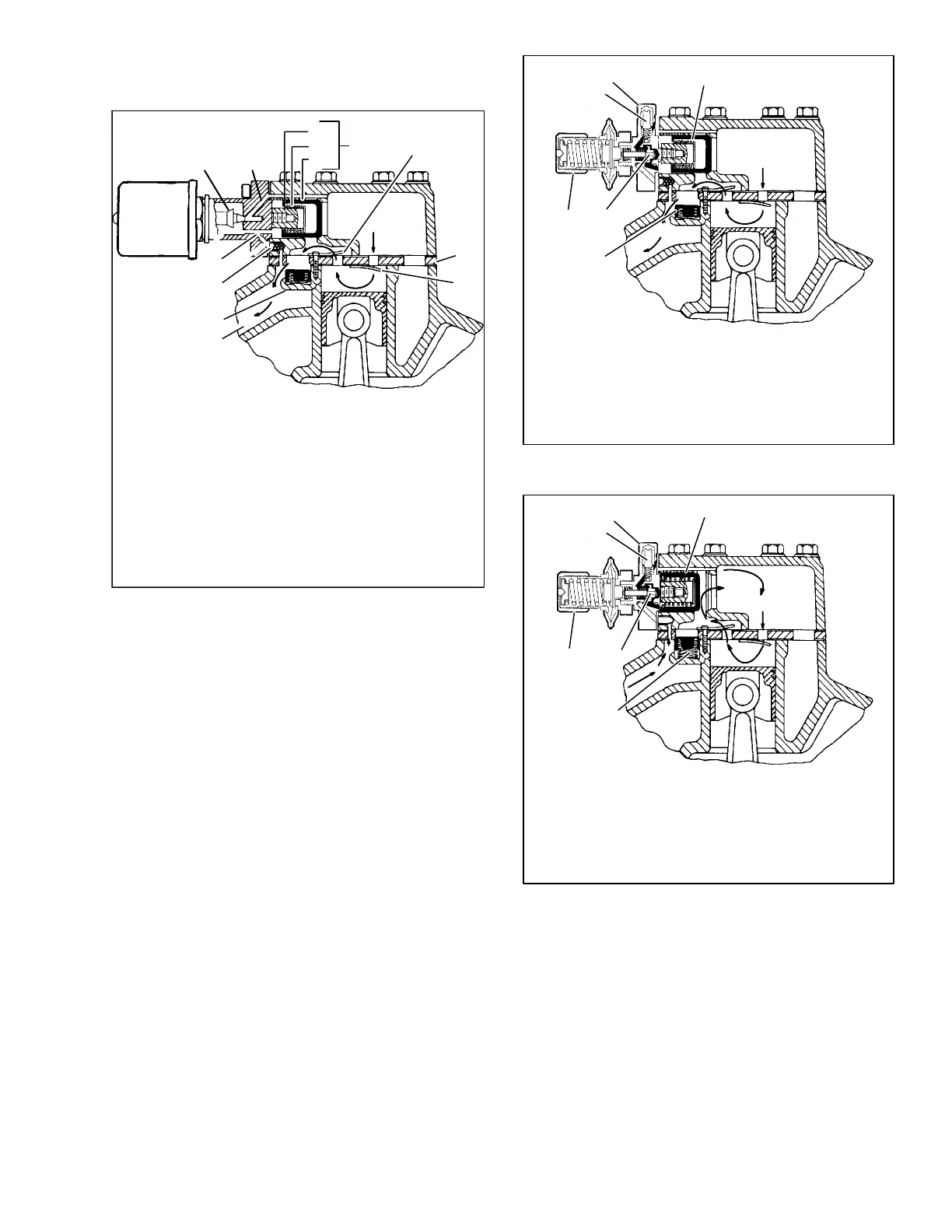
The loaded cylinder bank will continue to operate fully
loaded until the solenoid valve control device is
energized and the gas bypass port is opened.
1. Solenoid Valve
2 Valve Stem
3. Gas Bypass Port
4. Spring Guide
5. Spring
6. Piston
7. Piston Bypass Valve
8. Bleed Orifice
9. Strainer
10. Suction Cavity
11. Cylinder Discharge
Valve
12. Valve Plate
13. Cylinder Suction
Valve
14. Discharge Piston
Check Valve
Assembly
15. Discharge Manifold
10
1
2
3
4
5
6
7
8
9
15
11
12
13
14
Figure 1-7. Electric --Operated Unloader --
Loaded Operation
1.5.2 Pressure-Operated Unloaders
The pressure-operated unloaders are controlled by
suction pressure and actuated by discharge pressure.
The unloader valve controls two cylinders. On startup,
controlled cylinders do not load up until differential
between suction and discharge pressure is 10 psi (0.68
bar).
During loaded operation, (Figure 1-8) when suction
pressure is above the valve control point, the poppet
valve (4) will close. Discharge gas bleeds into the valve
chamber; the pressure closes the piston bypass valve
(5) and the cylinder bank loads up. Discharge gas
pressure forces the discharge piston check valve (6)
open, permitting gas to enter the discharge manifold.
During unloaded operation, (Figure 1-9) when suction
pressure drops below the valve control point, the poppet
valve (4) will open. Discharge gas bleeds from behind
the bypass piston to the suction manifold. The bypass
piston valve (5) opens, discharge gas is recirculated
back to the suction manifold and the cylinder bank is
unloaded. Reduction in discharge pressure causes the
discharge piston check valve (6) to close, isolating the
cylinder bank from the discharge manifold.
1. Sealing Cap
2. Pressure Differential Adjustment Screw
3. Control Set Point Adjustment Nut
4. Poppet Valve
5. Piston Bypass Valve
6. Discharge Piston Check Valve
4
1
2
3
5
6
Figure 1-8. Pressure-Operated Unloader
Loaded Operation
1. Sealing Cap
2. Pressure Differential Adjustment Screw
3. Control Set Point Adjustment Nut
4. Poppet Valve
5. Piston Bypass Valve
6. Discharge Piston Check Valve
4
1
2
3
5
6
Figure 1-9. Pressure-Operated Unloader -
Unloaded Operation
 Loading...


