3-3 62--11052
3.5.1 Removal
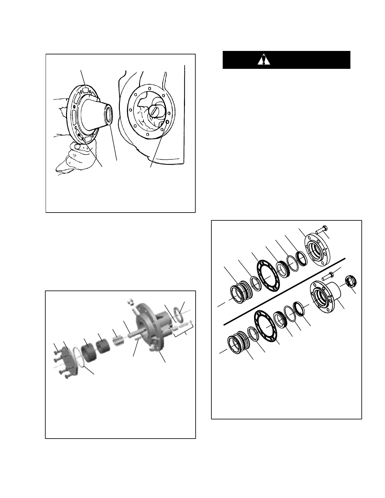
Remove eight capscrews and remove the oil pump
bearing head assembly, gasket and thrust washer. (See
Figure 3-5.)
1. Oil Pump & Bearing Head
2. Thrust Washer
3. Oil Pickup Tube
4. Oil Inlet Port
4
1
2
3
Figure 3-5. Oil Pump and Bearing Head Assembly
3.5.2 Disassembly, & Inspection
If it is determined that the oil pump is not operating
properly, the entire oil pump and bearing head assembly
must be replaced. Replacement parts for the pump are
not available except for the cover plate O--ring.
However, in the event the pump requires inspection or
cleaning, refer to Figure 3-6 for disassembly and
reassembly. Clean all parts; coat all moving parts with
compressor oil before proceeding with reassembly.
1 Capscrews
2 Cover
3 Eccentric Ring
4 Rotor
5 Idler
6 Shaft (Drive)
7 O-Ring
8 Oil Pump & Bearing
9 Dowel Pin
10 Relief Valve Assembly
11 Pins (2)
12 Thrust Washer
1
11
9
8
7
6
5
4
3
2
10
12
Figure 3-6. Oil Pump
3.5.3 Reassembly
a. Install the pump end thrust washer on the two dowel
pins located on the bearing head. (See Figure 3-5.)
CAUTION
Ensure that thrust washer does not fall off
dowel pins while installing oil pump.
b. Install the bearing head assembly with a new gasket
on the compressor crankshaft. Carefully push oil
pump on by hand ensuring that the thrust washer re-
mains on the dowel pins, the tang on the end of the
drive engages the slot in the crankshaft, and the oil
inlet port on the pump is aligned with the oil pickup
tube in the crankcase. The oil pump should mount
flush with the crankcase with the “TOP”stamp on the
pump oriented straight up. (See Figure 3-12)
c. Align the gasket and install the eight capscrews in the
mounting flange. Refer to Table 3-1, for applicable
torque values.
3.6 SHAFT SEAL
3.6.1 Disassembly
a. Remove 6 capscrews, remove the shaft gland plate
or clutch mounting hub. Remove rotor from top of bel-
lows assembly. (See Figure 3-7)
Used with
Housing Mounted Clutch
Standard
Shaft Seal
1 Bellows Assembly
2 Rotor
3 Gasket
4 Stator
5 O-Ring
6 Lip Seal
7 Clutch Mounting Hub
8HubNut
9 Gland Plate
10 Hex Head Screw
9
4
4
6
6
1
1
2
2
3
3
5
5
10
10
7
8
Figure 3-7. Shaft Seal
 Loading...


