Section 01: ENGINE
PA1553
22
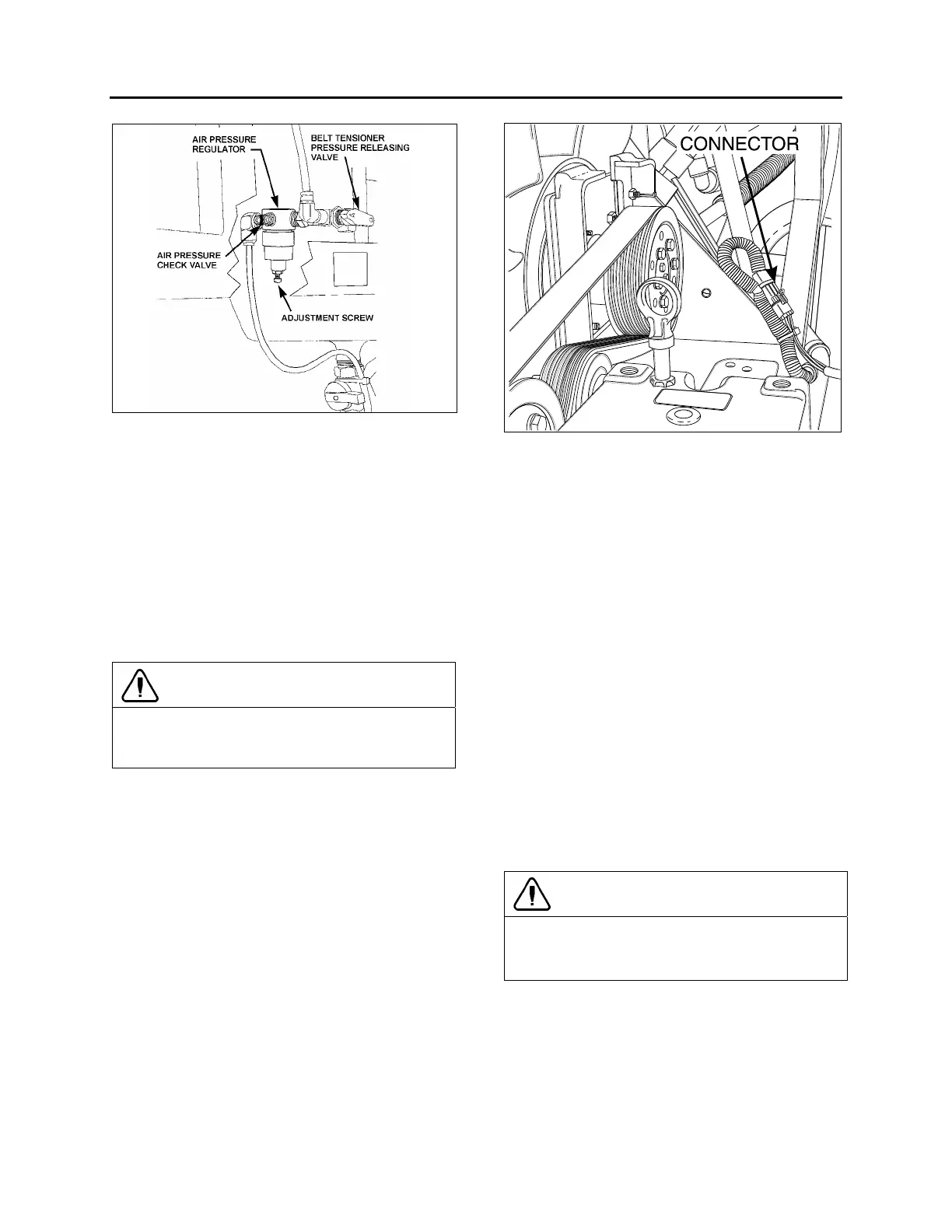
FIGURE 15: BELT TENSIONER VALVE
12200
4. Locate the belt tensioner pressure releasing
valve (Fig. 15). Turn pressure releasing valve
handle counterclockwise in order to release
pressure in belt-tensioner air bellows and
loosen belts. Remove the belts.
5. To release all pressure from the air system.
Refer to Section 12, BRAKES & AIR
SYSTEM for instructions.
6. Disconnect and remove the engine-air intake
duct mounted between air cleaner housing
and turbocharger inlet (1, Fig.17).
CAUTION
To avoid damage to turbocharger, cover the
turbocharger inlet opening to prevent foreign
material from entering.
7. Disconnect and remove the air intake duct
mounted between the air cooler outlet and
the engine intake (2, Fig. 17).
8. Disconnect and remove section of coolant
pipe assembly mounted between the radiator
outlet and the water pump inlet (3, Fig. 17).
9. Disconnect the coolant delivery hose located
close to the water pump.
10. Disconnect the electric fan-clutch connector,
close to the water pump (Fig. 17).
11. Dismantle the air bellows from the upper
bracket of the fan-drive assembly tensioner.
Remove the upper bracket (4, Fig. 17).
12. If necessary, remove the fan drive from the
engine compartment by removing the four
retaining bolts, washers and nuts securing
the fan drive to the floor.
FIGURE 16: ELECTRIC FAN-CLUTCH CONNECTOR
010XX
13. Disconnect and remove the air intake duct
mounted between the turbocharger outlet
and the air cooler inlet (5, Fig. 17).
14. Disconnect two vent hoses from the
thermostat housing and from the coolant pipe
assembly.
15. Disconnect and remove a section of coolant
pipe assembly mounted between the
thermostat housings and the radiator inlet.
16. Disconnect and remove the small hose
connected to the heater line valve and to the
water pump.
17. Disconnect the small heater hose located on
the cylinder head at the back of the engine.
18. Disconnect and remove the exhaust pipe
mounted between the turbocharger outlet
and the exhaust bellows. If necessary, refer
to Section EXHAUST SYSTEM under
MUFFLER REMOVAL AND
INSTALLATION".
CAUTION
To avoid damage to turbocharger, cover the
turbocharger outlet opening to prevent foreign
material from entering.
19. Disconnect the steel-braided airline from the
A/C compressor air bellows.
20. Disconnect the power steering pump supply
and discharge hoses. Cap hose openings
immediately to limit fluid loss. Remove
retaining clips from cradle (6, Fig. 17).
 Loading...


