100 Rockwell Automation Publication 2198-UM002L-EN-P - October 2021
Chapter 4 Connector Data and Feature Descriptions
DC Bus and Shunt Resistor Connector Pinouts
The 2198-Pxxx DC-bus power supply RC connector wires to an external passive
shunt when the internal shunt capacity is exceeded. The 2198-RPxxx
regenerative bus supply has no internal shunt and the RC connector wires to
an external active shunt.
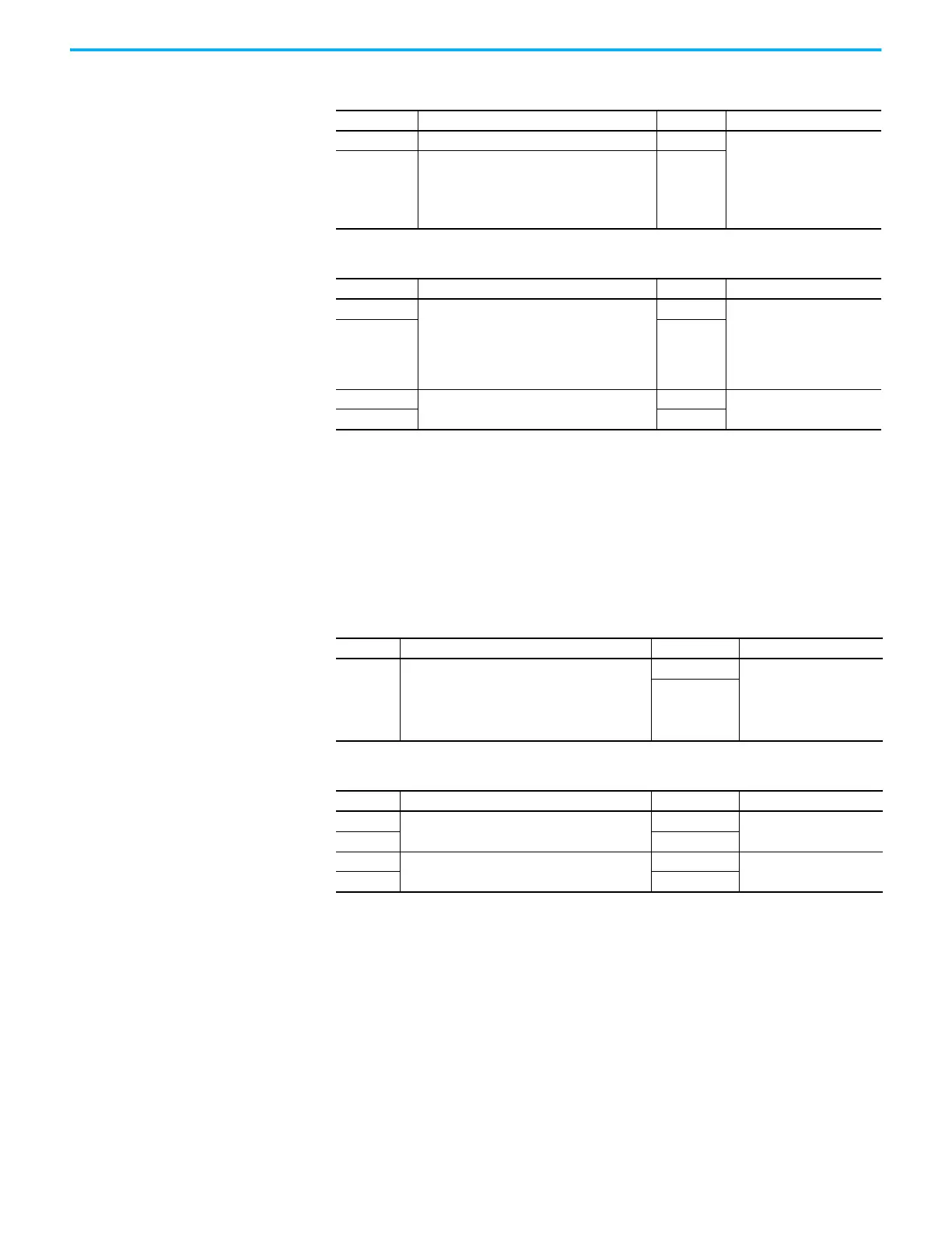
Table 32 - 24V Input Power Connector
CP Pin Description Signal Module
1 24V power supply, customer supplied 24V+ • DC-bus power supply
• Regenerative bus supply
• Inverters
• Capacitor module
• DC-bus conditioner module
• iTRAK power supply
2 24V common 24V–
Table 33 - Contactor Enable Connector
CED Pin Description Signal Module
OK+ Relay-driven contact that provides a 24V signal
to non-Kinetix 5700 inverters indicating that they
can draw power from the regenerative power
supply. This signal is intended for use with
Kinetix 6000, Kinetix 7000, or PowerFlex® drive
migration.
CONV OK+
Regenerative bus supply
OK– CONV OK–
EN–
Relay-driven contact that is used in the control
string for a three-phase power contactor.
CONT EN–
• DC-bus power supply
• Regenerative bus supply
EN+ CONT EN+
Table 34 - DC Bus Power Connector
DC Pin Description Signal Module
Bus bar DC bus connections
DC– • DC-bus power supply
• Regenerative bus supply
• Inverters
•Accessory modules
• iTRAK power supply
DC+
Table 35 - Shunt Connector
RC Pin Description Signal Module
1
Passive shunt connections
SH
DC-bus power supply
2DC+
1
Active shunt connections
DC–
Regenerative bus supply
2DC+

 Loading...


