270 Rockwell Automation Publication 2198-UM002L-EN-P - October 2021
Chapter 7 Troubleshoot the Kinetix 5700 Drive System
Inverter Behavior
For the single-axis inverters and dual-axis inverters, only selected exceptions
are configurable. In the drive behavior tables, the controlling attribute is given
for programmable fault actions.
Actions define the drive behavior in response to specific conditions. The
Actions category includes Standard Actions and Safety Actions.
Standard Actions
When a control connection update fault (NODE FLT 01) occurs or a controller
connection loss fault (NODE FLT 06) occurs, it is possible with firmware
revision 11.001 and later, that other node faults can occur first, which triggers a
fault action of Current Decel & Disable. Without knowing if NODE FLT 01 or
NODE FLT 06 will occur first on a connection loss fault, we recommend that
you do not change the default connection loss setting of Current Decel &
Disable.
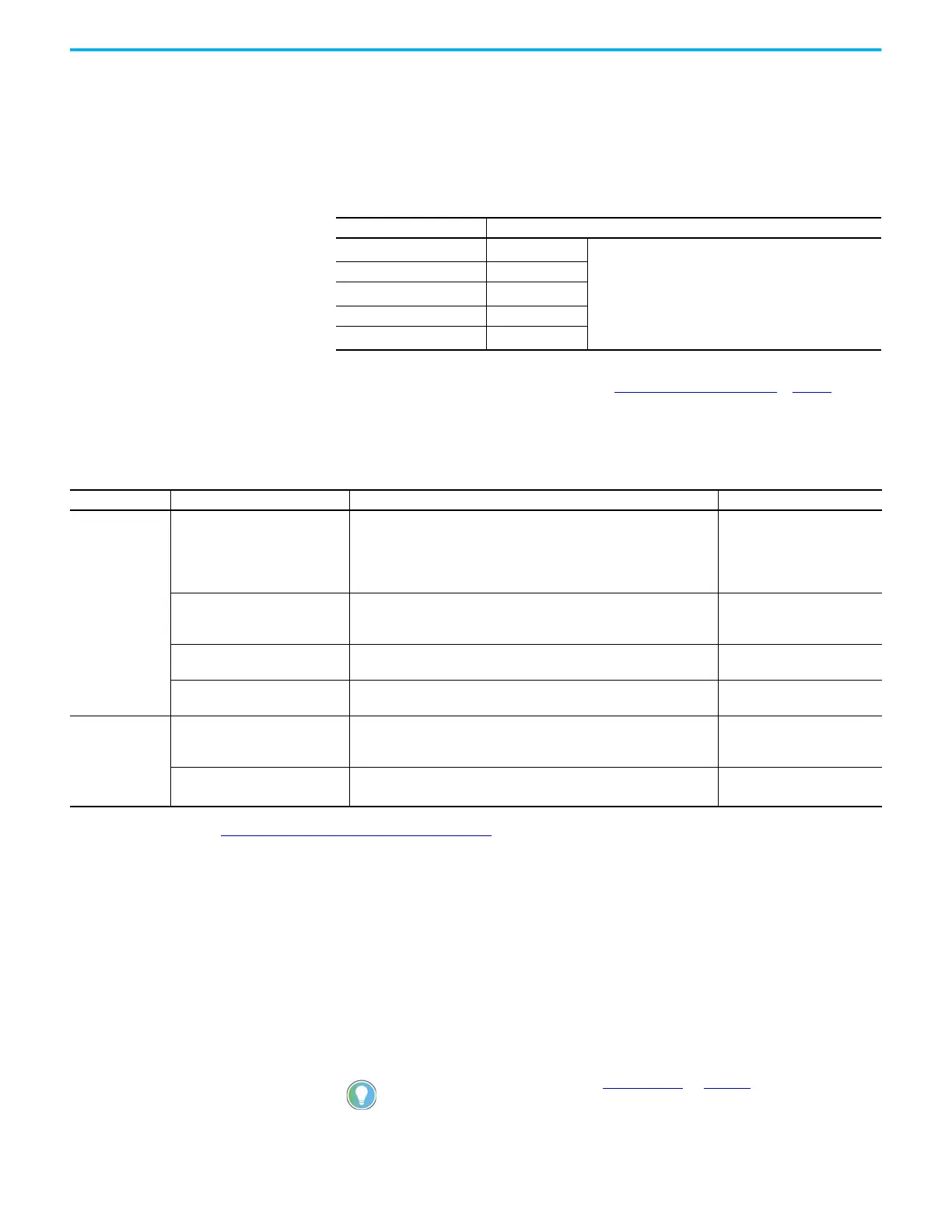
Table 147 - Configurable Stopping Actions
Stopping Action Description
Ramped Decel & Hold
(1)
(1) Ramped Decel is available only when General>Axis Configuration is set to Velocity Loop or Frequency Control.
Most control
The best available stopping action is the one that maintains
the most control over the motor. However, not all faults
support every stopping action.
Current Decel & Hold Most control
Ramped Decel & Disable
(1)
Less control
Current Decel & Disable Less control
Disable & Coast
(2)
(2) When configured for Frequency Control (induction motors only), select Decel & Disable only when the Current Limiting
feature is enabled. For more information on this feature, see Current Limiting for Frequency Control on page 402.
Least control
Table 148 - Actions Definitions
Action Category Action Name Action Trigger Condition Available Actions
Standard
Disable (MSF) Stopping Action Execution of an MSF motion instruction.
• Ramped Decel & Hold
• Current Decel & Hold
• Ramped Decel & Disable
• Current Decel & Disable
• Disable & Coast
Connection Loss Stopping Action
Loss of the motion connection (for example, inhibiting the module or a
network cable disconnect).
• Ramped Decel & Disable
• Current Decel & Disable
• Disable & Coast
Motor Overload Action Receiving MTR OVERLOAD fault.
•Current Foldback
•None
Inverter Overload Action Receiving INV OVERLOAD fault.
•Current Foldback
•None
Safety
Safe Torque Off Action
Transition from logic 0 to 1 of the SafeTorqueOffActiveStatus axis tag, which
indicates a safe torque-off action was commanded (STO).
(1)
• Ramped Decel & Disable
• Current Decel & Disable
• Disable & Coast
Safe Stopping Action
Transition from logic 0 to 1 of the SS1ActiveStatus or SS2ActiveStatus axis
tag which indicates a safe stopping action was commanded (SS1, SS2).
(2)
• Ramped Decel
(3)
•Current Decel
(1) This action is executed only if the axis tag transitions due to a requested STO, not if it was triggered by another safe-stop function (SS1, for example).
(2) See Knowledgebase Technote: Kinetix 5700 ERS4 Drive based SS1 monitored - Stopping method
for more information.
(3) Applies to only Velocity Control mode.
Use DLR ring topology (see Ring Topology on page 30) for applications
where the possibility of connection loss must be minimized.

 Loading...


