Rockwell Automation Publication 2198-UM002L-EN-P - October 2021 159
Chapter 5 Connect the Kinetix 5700 Drive System
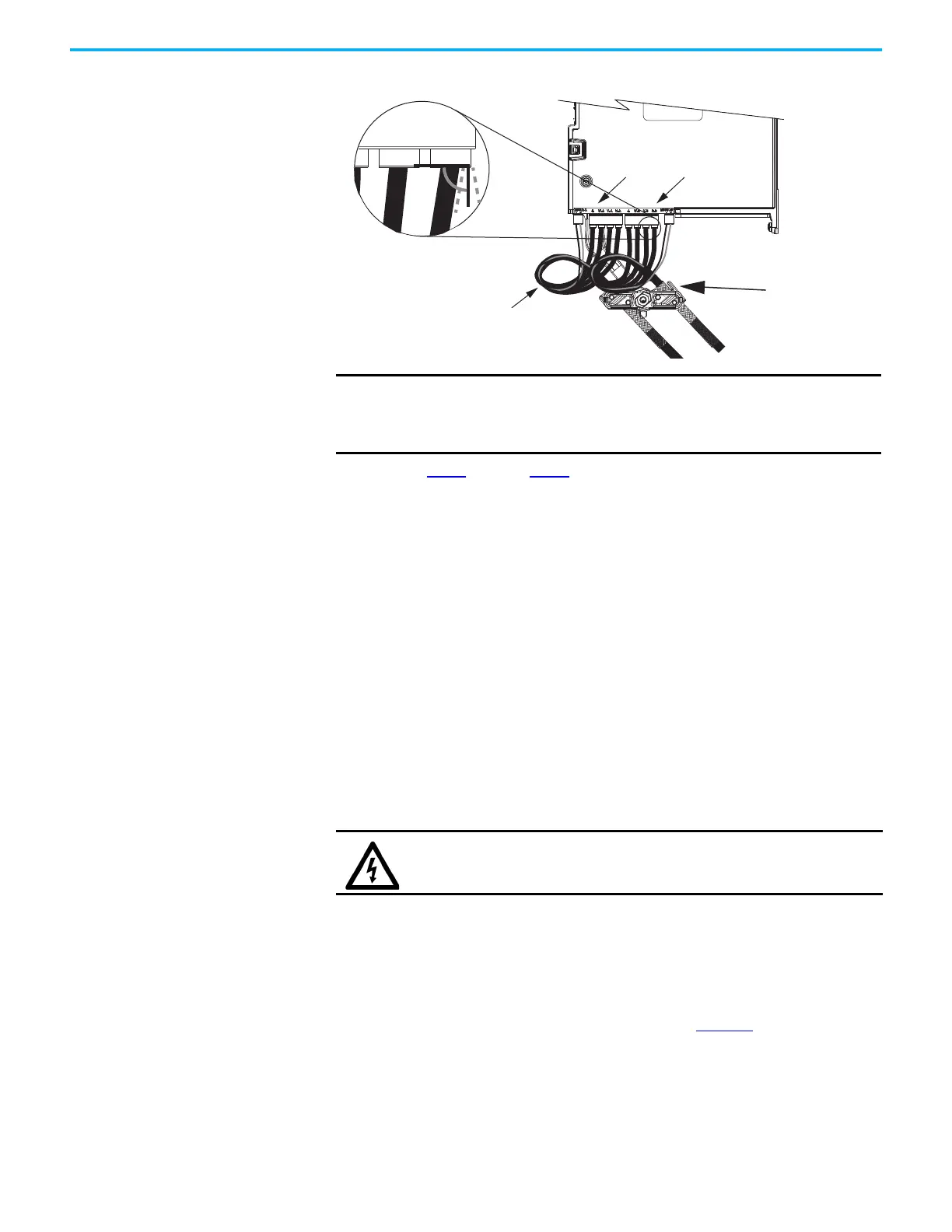
Figure 103 - Dual-axis Inverter Cable Installation (series A and B, 12 and 10 AWG cable)
4. Repeat step 1 through step 3 for each dual-axis inverter.
Single-axis Inverter Power/Brake Cable Installation
All single-axis inverters include a cable-shield clamp bracket that is designed to
ground (bond) 2090-CPBM7DF cable shields with the drive chassis.
• 2198-S086-ERSx, 2198-S130-ERSx, and 2198-S160-ERSx single-axis
inverters include a two-position cable-shield clamp that accommodates
10, 8, 6, 4, and 2 AWG power conductors. The clamp bracket is connected
to the motor power connector and ships with the drive.
•2198-S263-ERSx and 2198-S312-ERSx single-axis inverters include a
single-position cable-shield clamp that accommodates 4 and 2 AWG
power conductors. The clamp bracket ships with the drive, but requires
some assembly.
2090-CPBM7DF (series B) 10 AWG cables are designed for use with
Kinetix 5700 single-axis inverters and do not require any modifications.
For single-axis inverters, the 2090-CPBM7DF (series A) cable power
conductors, 102 mm (4.0 in.), require adjustment only when the smaller (upper
position) clamp is used. The upper position is for smaller cables (10, 8, and 6
AWG). The lower position is for larger cables (4 and 2 AWG). We recommend
that you measure from the edge of the cable jacket (that is covered with heat
shrink) and trim the power conductors as shown in Table 94
.
Clamps Compressed
Around Shields Close
to the Heat Shrink
Dual-axis Inverter
(side view)
Motor Power (MP) and
Motor Brake (BC) Connectors
Kinetix 2090-CPBM7DF
Power/Brake Cables
Service loops provide stress relief and the
conductors enter into the motor and brake
connectors at approximately 90°
(between 75 and 105° is acceptable).
75°…105°
Entry Into
Connectors
IMPORTANT
Avoid sharp bends in the power and brake conductors. You must
route the power and brake conductors from where they exit the
clamp and enter the motor and brake connectors so that stress-relief
bends or service loops are formed.
SHOCK HAZARD: To avoid hazard of electrical shock, make sure shielded
power cables are grounded according to recommendations.

 Loading...


