388 Rockwell Automation Publication 2198-UM002L-EN-P - October 2021
Appendix D Maximum Motor Cable Lengths for Kinetix 5700 Power Supplies
Third-party Motor
Configurations
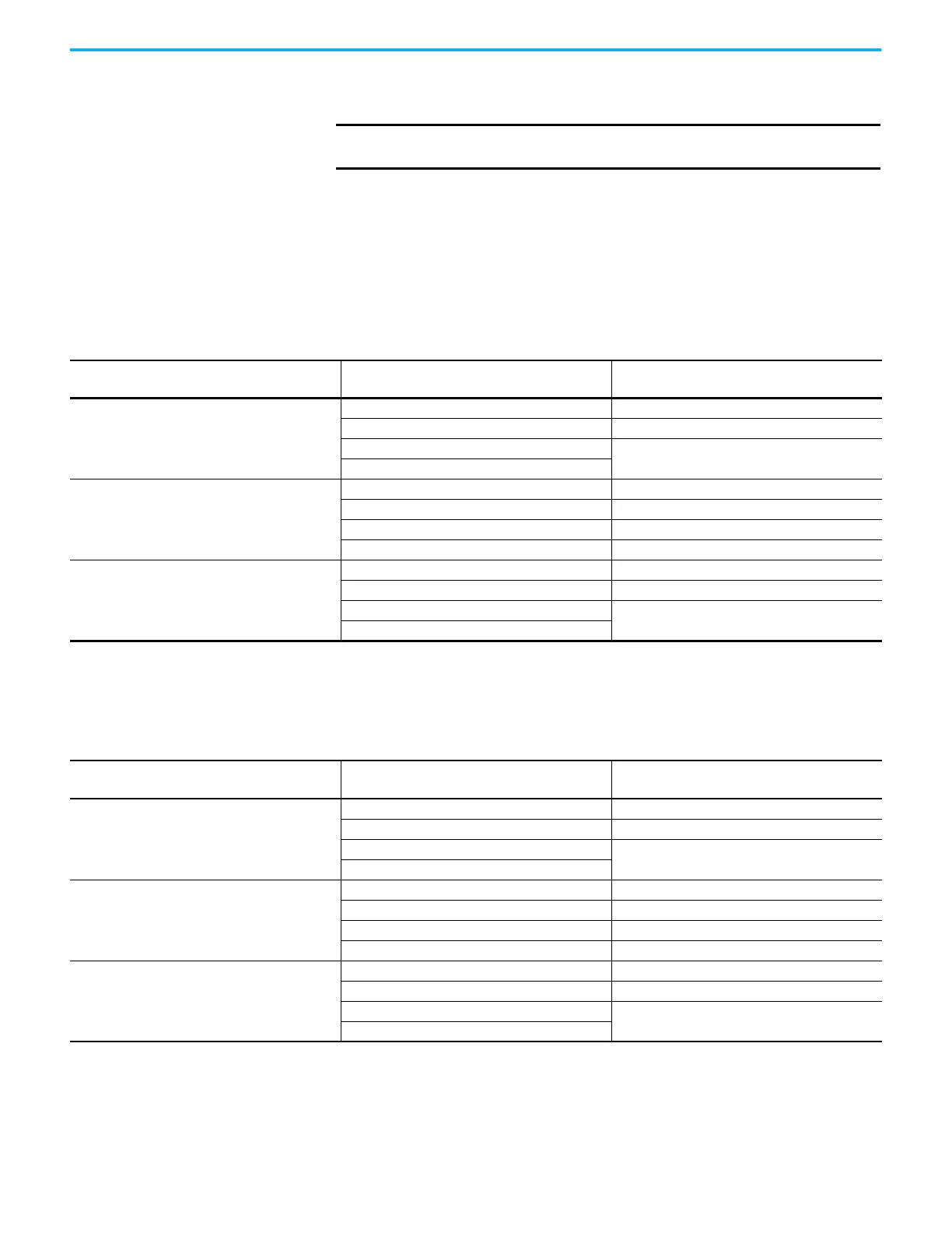
These tables provide maximum drive-to-motor cable lengths for third-party
motors with Kinetix 5700 common-bus supplies.
DC-bus Power Supply Configurations
These tables assume that no output reactor is used between the inverter and
the motor. Contact Technical Support for help when applying output reactor
solutions.
IMPORTANT
Kinetix 5700 drive systems do not support the use of disconnection
devices between the servo drive and motor.
Table 193 - DC-bus Power Supply (480V AC input)
AC Input Power Source Type
Motor Insulation Rating
(1)
Drive-to-Motor Cable Length, max
(2)
m (ft)
WYE Grounded
1000V –
1200V 15 (49.2)
1488V
90 (295)
1600V
Delta Corner Grounded
1000V –
1200V –
1488V 30 (98.4)
1600V 90 (295)
• WYE Impedance Grounded
(3)
• WYE Ungrounded
(4)
• Delta Ungrounded
(4)
1000V –
1200V 15 (49.2)
1488V
90 (295)
1600V
(1) Motor Corona Inception Voltage (CIV) or Partial Discharge Inception Voltage (PDIV) ratings for motor phase-to-ground and phase-to-phase insulation systems.
(2) Cable lengths are estimated assuming nominal DC-bus voltage at nominal AC line input voltage. Operation at high AC line voltage or increased DC-bus voltage for prolonged periods of time
can cause additional stress to the motor insulation and can cause premature motor failure.
(3) Impedance grounded systems running in ground fault conditions, for prolonged periods of time, cause additional stress to the motor insulation and can cause premature motor failure.
(4) Unbalanced, floating, ungrounded systems can cause additional stress to the motor.
Table 194 - DC-bus Power Supply (400V AC input)
AC Input Power Source Type
Motor Insulation Rating
(1)
Drive-to-Motor Cable Length, max
(2)
m (ft)
WYE Grounded
1000V 10 (32.8)
1200V 50 (164)
1488V
90 (295)
1600V
Delta Corner Grounded
1000V –
1200V 15 (49.2)
1488V 50 (164)
1600V 90 (295)
• WYE Impedance Grounded
(3)
• WYE Ungrounded
(4)
• Delta Ungrounded
(4)
1000V 10 (32.8)
1200V 50 (164)
1488V
90 (295)
1600V
(1) Motor Corona Inception Voltage (CIV) or Partial Discharge Inception Voltage (PDIV) ratings for motor phase-to-ground and phase-to-phase insulation systems.
(2) Cable lengths are estimated assuming nominal DC-bus voltage at nominal AC line input voltage. Operation at high AC line voltage or increased DC-bus voltage for prolonged periods of time
can cause additional stress to the motor insulation and can cause premature motor failure.
(3) Impedance grounded systems running in ground fault conditions, for prolonged periods of time, cause additional stress to the motor insulation and can cause premature motor failure.
(4) Unbalanced, floating, ungrounded systems can cause additional stress to the motor.

 Loading...


